

Water Rules & Regulations
Rules covering water service, permits, infrastructure, and material specifications.
Home > About BPU > Policies > Water Rules & Regulations
Water Rules & Regulations
Permits
Definition of Permit:
A Water Service Permit is a written document issued by the Board’s Plumbing Desk authorizing work to be performed. The purpose of these permits is to ensure that only qualified persons engage in this work. Permits are required under Section 6.00 of the General Policies Applying to Water Services.
Classification of Permits
Permits are defined as follows:
a) Water Service Permits are required where taps are to be made and new services are to be installed.
b) Water Service Maintenance Permits are required when an existing service is to be altered, extended, repaired, renewed or when the service is to be disconnected at the main.
Application for a Permit:
Plumbers must submit plans and/or plat plans in accordance with Section 6.00 and applicable sections of the General Policies Applying to Water Service for approval before applying for a permit.
Issuance Prior to Work:
No work in connection with the tapping of any main or the introduction of water into any premises (public or private) shall be done, nor shall any water service be altered, repaired, replaced or extended without prior issuance of a permit authorizing the performance of such work. When the plumber must perform emergency work, during other than normal working hours, the Water Operations Department shall be notified by telephone prior to the starting of such work and the plumber shall secure the permit on the next regular working day. See Section 5.02 of the General Policies Applying to Water Service for inspection of service connections.
Plumbers Not to Secure Permits for Others:
A Master Plumber’s or Journeyman Plumber’s license is not transferable, and any Master Plumber shall subject himself to suspension if he attempts to procure or procures a water permit for the benefit of anyone other than himself.
Permits Not Transferable:
Permits are not transferable and are only valid for the applicant to whom issued and for the job described thereon.
Permit Fees:
The applicant will pay all charges for tapping, meters, and meter setting at the time of procuring the permit.
a) Charges for tapping, meters and meter setting shall be in accordance with the schedule of prices. In the event that the permit is not used, these charges shall be refunded.
b) Whenever the original permit is lost, a duplicate permit must be secured.
Delinquent Permit/ Payment:
No permits will be issued to anyone who is holding a delinquent permit or delinquent on past invoices related to Development projects.
Issuance of Permits:
Permits shall be issued by the Board’s Plumbing Desk to qualified applicants only after all the requirements are satisfied. Permits are issued subject to a water main being in front of or adjacent to the property to be served. If the property is large enough to permit subdividing at a later date, it will be necessary for the water main to front the subdivided property on which the facility to be served is constructed.
Qualification of Applicants:
Applicants shall be prepared to show proof of qualification at the time of application and shall procure permits for themselves and no other. Permits shall be issued only to the following:
a) Plumbers licensed by the city of Kansas City, Kansas, may obtain permits from the Board to perform work in establishing a new water supply or to alter an existing water supply.
b) Licensed automatic sprinkler system contractors who are to install fire protection systems after the first control valve or blind flange inside the building.
(i) Licensed plumbers shall install the fire protection system from the water main to the first control valve or blind flange inside the building.
(ii) Licensed automatic sprinkler contractors shall install the fire protection system after the first control valve or blind flange inside the building.
c) Licensed lawn irrigation contractors who are to install lawn irrigation or sprinkler systems after the first control valve and meter.
(i) Licensed plumbers shall install the lawn irrigation system from the water main to the first control valve and meter.
(ii) Licensed lawn irrigation contractors shall install the lawn irrigation system after the first control valve and meter.
Required Conditions:
Prior to receiving the permit, the applicant must submit the following documents for examination at the Plumbing Desk:
a) Plumbers must submit plans and/or plot plans of multi-family, commercial and industrial buildings for water service recommendations. Plot plans shall be submitted for domestic service for single-family dwellings.
b) Payment in the amount of all the charges associated with the proposed work.
Required Procedure:
Builder or Plumber shall complete an Application for Water Service and an application for a permit. The documents shall contain the following information:
a) The name of the person for whom the work is to be performed or the owner of the property served. The correct address and other legal description where work is to be performed. Additional information as noted on the form.
Return of Permits:
Each permit must be returned to the KCBPU Inspector when the final inspections are made. Returned permits must contain a complete report of all work done, and such report shall be of form and content as prescribed on the permit.
a) All permits and reports shall be made out with typewriter or legibly written with ink. The applicant must sign reports. Each report must state the date on which the work was completed and must be signed by the inspector.
Rejection for Inadequacy:
A permit, which fails to show clearly and accurately all of the required information, shall be rejected, and the applicant shall make corrections immediately. Permits returned without being signed by the inspector will be rejected.
Permit Cancellation:
The Manager of Water Operations shall be authorized to cancel for just cause any permit issued. The permit shall expire within 120 days from the issuance of the Permit.
Water Services
Definition:
A Water Service is the piping installed from the water main to that portion of the interior piping which is regulated by the Building Code.
Classification of Services:
Water Services are classified into two categories: Small Services and Large Services. The components of a small service are a corporation stop, tap saddle, copper tubing, meter yoke, meter, backflow device, meter box, stop and waste valve. The components of a large service are a tapping sleeve (or tee) and valve, a valve box, pipe, meter, stop and waste valve, backflow device and drain connections complete with valves and by-pass piping. Large Services may be for a domestic water service or fire line.
General Installation Requirements:
All service lines shall conform to the following requirements:
- a) Service connections are to be made in front of or adjacent to the property to be served.
- b) Service lines are to be run perpendicular to the main from the main to the meter box. The meter box shall be located between the back of curb / edge of asphalt and the property line or right of way as determined by BPU. In general, the meter box shall be located at the property line.
- c) Service lines shall be laid at least ten feet horizontally from any existing or proposed drain or sewer line. When it is impossible to obtain vertical or horizontal separation, the sewer line shall be encased in concrete per the Kansas Department of Health and Environment guidelines and BPU standards.
- d) Where service lines must cross over sewers, storm drains, or sanitary sewers, the service line must be laid at such an elevation that the bottom of the service line is at least twenty-four inches above the top of the sewer. This vertical separation must be maintained for that portion of the service line located within ten feet horizontally of any sewer or sewer line that it crosses, said ten feet to be measured as the normal distance from the service line to the sewer.
- e) Service lines shall have a cover of not less than three feet six inches (3′-6″).
- f) No service line will be less than 3/4 inches in diameter.
- g) The appropriate backflow prevention assembly will be installed on each water service in accordance with Board policy.
- h) Service connections to polyethylene-encased water mains will require the service to be encased in polyethylene for the first ten (10) feet of the copper service on the outlet side of the corporation, tapping valve or gate valve. Installation through the meter pit shall conform to the applicable standard drawings in the Rules and Regulation Manual.
- i) Water services shall be installed in accordance with the General Policies Applying to Water Service in addition to this Rules and Regulations Manual.
- j) All PVC and HDPE water services shall use 14-gauge tracer wire.
Installation Requirements for Small Services:
All Small Service Lines shall conform to the following requirements:
When installing small service lines, the following material requirements apply to the specific service size:
- a) (3/4 inch and 1 inch): Type “K” copper only shall be used between the main connection and the customer’s first control valve (ball valve or meter box). Type “K” copper or polyethylene plastic tubing (HDPE 4710 DR 11 rated at 200 psi) shall be used between the customer’s meter box and the “Stop and Waste” valve located immediately within the basement or building wall. Compression or fused fittings shall be used between copper and HDPE material at the transition into the meter box. Plastic stiffeners shall be installed when compression fittings are used.
- b) The line shall be laid with an expansion loop located as near to the corporation stop as possible. This loop shall be in the form of a half “S” bend and be at least six (6) inches off the centerline of the run.
- c) (1 ½ inch and 2 inch): Type “K” copper or HDPE 4710 DR 11 rated for 200 psi shall be used between the main connection and the “Stop and Waste” valve located immediately within the basement or building wall. Material through the meter box shall be in accordance with the standard drawings utilizing copper / brass (no lead) pipe beginning and ending six (6) feet on each side of the meter pit. Fused fittings shall be used between copper and HDPE material at the transition into the meter box.
- d) No union or compression fitting shall be permitted between the corporation stop and the curb stop or meter box where the distance is less than 100 feet.
- e) No sweat joints will be permitted on any portion of the buried service line.
- f) Each small service line shall be fitted with a stop and waste valve immediately on entering a building. The “Stop and Waste” valve shall be in accordance with the current Water Department Specifications.
- g) A pressure-reducing valve is permitted on the outlet side of the meter and before the backflow device.
- h) Services supplying duplexes shall be individual connections at the main with separate ¾-inch services with individual meters in a separate meter box. Services shall be at least 3 feet apart.
- i) For meter box installations, Type “K” copper shall be used six (6) feet on the inlet and outlet side of the meter box. Installations using HDPE shall be a pack joint fitting transition from HDPE to Copper CTS at the 6-foot transition. Plastic stiffeners shall be installed when compression fittings are used.
- j) Compression type connections only shall be used on Type “K” copper, three-quarter (¾) to two inches (2″) in size. Plastic stiffeners shall be installed when compression fittings are used.
Installation Requirements for Large Services:
Large service lines are services that are three inches in diameter (3 “) and larger shall conform to the following material requirements:
- a) 3 inch: Three-inch services shall be either Type “K” copper, polyethylene encased ductile iron pipe, HDPE 4710 DR11, rated at 200 psi from the first control valve to the “Stop and Waste” valve located immediately inside the building wall.
- b) Service lines larger than three inches in diameter: Polyethylene encased ductile iron pipe or PVC C900 DR 14 from the first control valve to the “Stop and Waste” valve located immediately inside the building wall.
- c) Large service lines shall be connected to the main with a tapping sleeve and valve or a tee and gate valve. Valves shall turn clockwise to open, and shall be in accordance with Water Department specifications.
- d) The tapping valve or gate valve on large service connections shall be fitted with a roadway box that conforms to current Water Department Specifications. Valves shall also be fitted with a valve base where necessary.
- e) All large service lines shall be fitted with a “Stop and Waste” or entrance valve immediately on entering a building. The valve on a backflow prevention device shall not be misconstrued as being the “Stop and Waste” or entrance valve.
- f) The tapping sleeve and valve or tee and valve shall be installed by the Board of Public Utilities and paid for by the developer or plumber before a Water Service Permit will be issued.
- g) All ductile iron services and fire lines shall be encased in polyethylene for the entire length of pipe.
- h) All fittings for PVC pipe shall be ductile Iron Fittings AWWA C153 and encased in polyethylene.
Maintenance of Services:
The Water Operations Department shall maintain all service lines from the main to the first control valve, but not the outlet side of the control valve. On small service piping the first valve may be either the curb stop or the shut off valve at the meter yoke for outside meter sets, whichever is nearer to the water main. The owner shall maintain the service line from the outlet side of the first control valve into the building being supplied. Repairs to any section of the water service line shall be performed in an approved manner using approved materials. An insulating bushing shall be used when a new copper service line is connected to an existing ferrous service line other than copper.
Abandonment of Services – General:
Services must be disconnected at the main in the event of building demolition or alteration. Abandonment of services shall be performed under a Water Service Maintenance Permit in the following manner:
- a) On small service connections, the corporation stop shall be uncovered, the corporation stop turned off, the service line disconnected, and the threads cut off on the outlet side. All curb boxes and meter tiles, whether on public or private property, shall have all rings, covers, and lids removed, wall casings removed or broken down to a minimum of one foot below grade and backfilled to grade.
- b) On large service connections, the abandonment shall be performed in a manner specified by the Water Department.
Abandonment of Services for Building Demolition:
When a building is to be razed or moved, all unnecessary services to the premises shall be abandoned in accordance with the following:
- a) A licensed Plumber shall procure a Water Service Maintenance Permit for each service to be abandoned and shall perform all work necessary to abandon small services.
- b) The Plumber shall be responsible for the excavating and backfilling of all holes and repair of street cuts.
- c) On small services, the Plumber shall perform the work of cutting off corporation stop outlet threads, abandonment of the curb box and of meter tile and lid. Inspection shall be made before backfilling.
- d) When services larger than one (1) inch in size are to be abandoned and the connection to the main is other than corporations, the Plumber will be required to pay the Board a fee to disconnect the service based on the cost of material, labor and overhead. The plumber shall provide an excavation of adequate size to allow the work to disconnect the water service by the Board to be performed satisfactorily. Removal of the meter pit lid as required and backfilling of the excavation and meter pit shall be the plumber’s responsibility.
Abandonment of Service for Building Alterations:
When a building is to be altered, any service abandonment shall be considered the same as the abandonment for building demolition.
Reconnection of Services:
When a plumber is required to repair services, which have been disconnected or turned off at the corporation stop by the Board, he shall leave the water off at the curb stop. Where the threads on the corporation stop have been cut off, a new service line, Water Service Maintenance Permit for renewal and tap will be required. Street repair is the responsibility of the plumber.
Installation requirements for Specific Activities:
The Board shall maintain a list of installation requirements for specific activities or conditions. The list shall, upon request, be furnished to any customer performing any of the specific activities.
When two or more of the activities are conducted, or conditions exist, on the same premises and served by the same water service, the most restrictive method shall be required to be utilized or installed in compliance with the standard specifications adopted by the Board.
Customer must pay the cost in advance the estimated cost as determined by KCBPU. Additional payments by the customer and or refunds or credits by KCBPU resulting from adjustments to such estimate and reconciliation of the final costs shall be made in accordance with this policy as described herein.
Double Valve: The term “Double Valve” shall mean domestic water services or fire protection lines shall be connected to the main by cutting in a service tee, installing three gate valves, and two solid sleeves on the main. Line valves on the main shall be the same nominal size as the main. All buried valves shall turn clockwise to open and shall be in accordance with current Standards and Specifications. The BPU may reduce the number of line valves if there is an existing line valve within 100 feet of the proposed service.
| Description | Double Valve Required |
|---|---|
| Aircraft and missile plants | Yes |
| Ambulatory Surgery Center | Yes |
| Animal clinics and animal grooming shops | Yes |
| Any premise where a cross-connection is maintained | No |
| Automotive repair with steam cleaner, acid cleaning equipment, or solvent facilities | No |
| Auxiliary water systems | No |
| Birthing Centers If they have a large service | Yes |
| Bottling plants, beverage or chemical | No |
| Breweries | No |
| Buildings greater than three (3) stories or greater than thirty-four (34) feet in height from curb level | No |
| Buildings with house pumps and/or potable water storage tank | No |
| Buildings with landscape fountains, ponds, or baptismal tanks | No |
| Buildings with sewage ejectors | No |
| Canneries, packing houses, and reduction plants | Yes |
| Car wash facilities | Yes |
| Centralized heating and air conditioning plants | No |
| Chemical plants | Yes |
| Chemically treated potable or non-potable water systems | No |
| Civil works (government owned or operated facilities not open for inspection by the Board) | No |
| Commercial laundries | No |
| Commercial Service | No |
| Dairies and cold storage plants | No |
| Daycare | No |
| Dialysis Centers | No |
| Dye works | No |
| Film processing laboratories | No |
| Fire systems – American Water Works Association Classes 4, 5 | Yes |
| Fire systems – American Water Works Association Classes 1, 2, 3 | No |
| Food processing plant | Yes |
| High schools and colleges; RP * | Yes |
| Holding tank disposal stations | No |
| Home Health Agencies | No |
| Hospice | Yes |
| Hospitals (major complexes) | Yes |
| Irrigation systems | No |
| Laboratories using toxic materials | No |
| Locations with more than 100 people (i.e. stadiums, sport complexes, hotels, convention centers) | Yes |
| Long Term Care Facilities (i.e. nursing homes) | Yes |
| Manufacturing, processing, and fabricating plants using toxic or non-toxic materials | Yes |
| Medical and dental buildings, sanitariums, rest and convalesce | Yes |
| Mobile home parks | No |
| Motion picture studios | No |
| Multiple services-interconnected | Yes |
| Oil and gas production facilities; RP | No |
| Paper and paper production plants | No |
| Plating plants | No |
| Portable insecticide and herbicide spray tanks | No |
| Power plants | Yes |
| Preschool | Yes |
| Radio active materials processing facilities | No |
| Restricted, classified, or other closed facilities | Yes |
| Rubber plants | No |
| Sand and gravel plants | No |
| Schools | Yes |
| Sewage and storm drainage facilities | No |
| Shopping centers; DC | No |
| Street sweepers, steel wheeled rollers | No |
| Transplant Centers | Yes |
| Water trucks, water tanks or hydraulic sewer cleaning equipment | No |
Tapping
Classification of Taps:
Taps are classified as small taps and large taps.
- a) A small tap for ¾” and 1” services is the cutting of threads directly on the wall of the water main or utilizing a tapping saddle for PVC mains or fused saddle for HDPE mains and the insertion of a corporation stop. For 1½”-2” services, a tapping saddle is used. For water mains 2” or smaller either a tapping saddle or tee will be installed.
- b) A large tap is a connection to the main made by employing a tapping valve and sleeve or saddle. A tee and valve shall also be considered a large tap.
General Requirements for Taps:
All taps shall be subject to the following requirements:
- a) Tapping shall be performed only by the Water Operations Department.
- b) Taps shall be located within the property lines of the property to be served.
- c) Taps shall be made on the side of the main nearest the premises to be served except where otherwise approved.
- d) Responsibility for excavation, protection of excavation and backfilling shall rest on the licensed plumber named on the permit.
- e) Excavations must be free of water and debris so that the tapper and inspector can perform their tasks without delay. Shoring shall be required on excavations greater than 5 feet deep or when the existing soil condition dictate. The main shall be clean of all soil or debris. Should the excavation be in such a condition as to necessitate an additional trip by the tapper or inspector, the Plumber shall be charged for such additional trips at the prevailing rate. Refer to drawing A-167.
Requirements for Small Taps:
Small taps shall be subject to the following requirements:
- a) Small taps shall be made so that the corporation stop for ¾” and 1” services is inserted at approximately 45° on the top quadrant of the main. Taps for 1½” and 2” services shall be made horizontal to the main to facilitate installation of a roadway box.
- b) If small taps cannot be made in accordance with paragraph (b) above because of obstructions or conditions that cannot be changed, the manner in which the tap is to be made will be determined by the Water Operations Department.
- c) Manifold, two or three branch outlet connections will not be permitted.
- d) A small tap shall not be closer than eighteen (18) inches to a bell, spigot, valve or blow-off.
- e) Excavation shall be a minimum of three (3) feet wide (with the main) by four (4) feet long at elevation of the tap. The main shall have six inches of clearance under and six inches on the backside. The tap hole shall meet all OSHA standards.
- f) Small taps shall be spaced a minimum of three (3) feet apart.
Requirements for Large Taps:
Large taps shall be subject to the following requirements:
- a) On all 3” services, a 4-inch large tap shall be made and connection thereto shall be effected by a reducer supplied by the plumber.
- b) Large taps shall be made so that the tapping valve is horizontal to facilitate a vertical valve box installation on the tapping valve.
- c) Large taps shall not be made closer than two (2) feet from bell end of the pipe, valve, blow-off or fitting.
- d) The excavation for a large tap shall extend seven (7) feet from the face of the main, five (5) feet along the main, and the main shall have twelve (12) inches of clearance under the main and sufficient space behind the main for thrust blocking. See Drawing
- e) All large taps 4-inch and larger shall be provided with thrust blocks. See Drawing
- f) The tapping valve on each large tap shall be provided with a block (rock, stone or brick) support, at least ten (10) inches square and two (2) inches thick, placed on a centerline with the valve stem. Supporting blocks are to have good bearing on undisturbed soil. The supporting blocking under the tapping valve is to be left permanently by the plumber. The cost of repairing failures of tapping sleeves and valves found without supporting blocks shall be charged to the plumber under whose permit the subject work was done.
Request for Taps:
The Plumber shall notify the Plumbing Desk 24 hours in advance to schedule a tap the following business day. When large taps are desired, the request must be made 48 hours in advance. The excavation for the tap must be inspected and approved by the Water Operations Department before scheduling the tap. It will be the responsibility of the plumber to protect the excavation during this period with steel plates, barricades or flashers.
Meter Sets
Definition:
A meter set is an assembly connected in the service line which consists of a meter, valves and a by-pass where specified.
General Requirements for Meter Sets:
All meter sets shall conform to the following requirements:
- a) All meters shall be set in an approved non-hazardous place and accessibility shall be maintained at all times.
- b) All meters shall be set in a horizontal position.
- c) The size of the meter shall never be larger than the service line in which it is installed.
- d) Meter sets for meters 1½ inch and larger will require a by-pass with a sealed by-pass valve.
- e) The plumber shall furnish and install all pipe, fittings and valves necessary for the meter set.
The Water Operations Department shall install meters after the customer has signed up for service with the Board’s Customer Service Department and the installation has been inspected.
Outdoor Meter Sets – Small Meters:
All outdoor meter sets for meters one inch and smaller shall conform to the following requirements:
- a) Meter sets shall be placed between the back of curb / edge of asphalt and the property line or right of way as determined by BPU. In general, the meter box shall be located at the property line.
- b) Meters shall be set in a pit and in the arrangement as shown on the Board’s standard meter pit detail drawing.
- c) Maintenance and testing of meters will be performed by the Water Operations Department. All meter pits are the property of the owner and shall be maintained by the owner.
Outdoor Meter Sets – Large Meters:
All outdoor meter sets for meters 1½ inch and larger shall conform to the following requirements:
- a) Meter sets shall be placed on private property in a suitable location as designated by the Board of Public Utilities. No inside locations allowed.
- b) Meters 1½ inch and larger shall be provided with a by-pass connection with a sealed valve.
- c) Maintenance and testing of meters will be performed by the Water Operations Department. Meter pits are the property of the owner and must be maintained by the owner.
Meters:
Meters 5/8 inch through 4 inch shall be purchased from the Board of Public Utilities’ Plumbing Desk when applying for water service. FMCT meters shall be purchased by the owner in accordance with the Board of Public Utilities Specifications.
Meter Sets for Serving Other Water Utilities:
When meters are set for serving other water utilities, they shall conform to all requirements herein set forth; and in addition, they shall include a double check valve assembly installed on the consumer side of the meter.
Changing Out of Meters:
The changing out of meters shall only be performed by the Water Operations Department. In the event that this procedure inconveniences a customer, he may request that his meter be changed after normal working hours; however, he will be required to bear the cost of this service in accordance with Board policy.
Relocation of Meter Pits:
The relocation of meter pits shall be performed in accordance with the Board’s Water Service Rules and Regulations.
Inspection
Definition of Inspection:
An inspection is an investigation and review by the Water Operations Department of work performed by others under a permit issued by the Board’s Plumbing Desk and which is evidenced by a certificate of inspection.
When Required:
Inspections are required on all work performed under a Water Service permit or Water Service Maintenance Permit.
Scope of Inspection:
The entire work as described on each permit shall be subject to inspection. If it is requested that work performed be inspected in phases, a certificate of inspection shall be required for each phase. Certificates covering all phases of the work performed must be submitted with the permit upon its return.
Time of Inspections (Large Services):
Inspections will be performed during normal working hours. When it is requested that inspections be performed at times other than normal working hours, the plumber making the request will be charged for the direct cost of such inspection.
Request for Inspection:
Plumbers shall make requests for inspections to the Board’s Plumbing Desk 24 hours in advance to schedule an inspection the following business day. Requests for inspection will be disregarded and the inspection not made if a permit for the work has not been issued.
Conditions for Inspections:
Service line excavations and trenches presented for inspection shall be free of water, debris, and other matter that would hinder the inspector.
- a) Where a copper service line is laid in a trench, the trench shall be left open for its entire length and the entire length of service line exposed to view.
- b) Where a ductile iron service line is installed in a trench, it may be backfilled before inspection except that all joints and fittings shall not be backfilled, but left exposed.
- c) Where a service line is bored, the excavations required for boring shall be left open and the portion of service line in these excavations shall be exposed to view. Installation shall follow the Unified Government’s standard for horizontal boring drilling.
Inspection of Large Services:
- a) Fire protection and domestic services four (4) inches and larger may be hydrostatically tested by others. All inspections of this type shall be by prior approval and arrangement of the Water Operations Department.
Extension of Water Mains
Extension Agreement:
When the customer desires a water main to be extended to furnish water service to any property for residential, commercial or industrial use, the customer (applicant) shall make a formal application and deposit with BPU an amount equal to the estimated cost of such connection, improvements or extension of the water distribution system, and shall sign and execute an agreement in a form satisfactory to BPU. If all work set forth in this agreement has not been completed within a two (2) year period, BPU may terminate the agreement or require an amendment including any increase in the initial deposit to offset any increase in construction cost.
BPU has two types of main extension agreements:
Plan A is for extensions made interior to the development. Water main extension costs are not refundable.
Plan B is for extensions exterior to the development. The initial cost of the extension shall be borne by the applicant. However, acreage charges shall be collected by the BPU from other property owners within the Benefit Area as water service is provided. These acreage charges are refunded to the customer who paid for the original extension. The acreage charge collected from other property owners will be proportional to the property area compared to the benefit area. Acreage charges shall not apply if the Board has an existing water main adjacent to the property. Acreage charges and customer refunds are discontinued after ten years.
Specifications:
The applicant shall pay an Engineering Design Services Fee as determined by the Board. The BPU’s Civil Engineering Department will prepare the water main design and estimated costs for all new developments. A BPU selected contractor will provide the water main installation.
The applicant shall submit a plat plan that has been approved by the Unified Government along with plan and profile drawings 90 days prior to the desired date for commencement of water main construction in the proposed development, showing streets, sanitary sewers, storm sewers, subsurface (rock) data or rock borings, sidewalks and the number and type of proposed structures. All data shall be submitted digitally in AutoCad dwg format. In an effort to respond in a timely manner to main extension requests, digital drawings will not include X-ref’s or Z-coordinates. The original design and estimated costs for water main extensions will be based on the plans submitted and any revision of those plans. Revisions that materially affect the original design and estimated costs may require an addendum to the original agreement or execution of a new agreement.
The length of the requested extension shall be that distance from the nearest existing distribution main of adequate capacity to the farthest point on the property being served or the last lot being served, as measured along the center line of existing and proposed street rights-of-way, unless a lesser distance shall be determined adequate by BPU.
The diameter and material of the main to be installed shall be determined by BPU, based upon a consideration of the following factors:
- a) Provisions of adequate service to prospective customers.
- b) Possible and contemplated future extensions of the main to be installed.
- c) Fire protection needs existing or anticipated in the area to be served.
If BPU desires to make the extension with pipe of a larger diameter than that reasonably required to serve the area to which the main is being extended, the additional cost for the larger diameter main shall be borne by BPU.
Estimated Cost:
The total estimated cost of the proposed water main extension will be prepared by BPU and the applicant shall receive one copy. The estimate shall include the cost of easements, pipe, fittings, valves, fire hydrants, rock excavation, miscellaneous material, labor, supervision, inspection, engineering, insurance, accounting, taxes, permits, construction equipment and tools, restoration of rights-of-way and overhead expenses. If the applicant fails to submit subsurface (rock) data or rock borings, the cost estimate will be prepared using ten percent (10%) solid rock, fifteen percent (15%) machine rock and seventy-five percent (75%) common soil excavation.
Upon completion of the water main extension, all costs will be determined. If the actual cost is less than the estimated cost, a refund of the difference shall be made to the applicant. If the actual cost is greater than the estimated cost, the applicant shall make an additional payment to BPU.
Construction:
After execution of the Agreement, BPU will attempt to construct the water main extension at a time more desirable to the applicant, however, BPU should be allowed a minimum of twelve (12) weeks from date of application to schedule its contractor for this work.
BPU’s Contractor shall furnish all labor, equipment, tools and material necessary for the extension of the water main. All equipment, materials, construction methods and tools shall comply with applicable code of local, state and federal authorities. All work in constructing the extension shall be subject to inspection and approval by BPU to ensure that such construction is in strict compliance with the construction specifications, drawings and plans.
Maintenance of the water main extension and appurtenances, street crossings and surface areas is BPU’s responsibility.
Special Conditions:
Whenever water main extensions are installed in other than dedicated public rights-of- way, the applicant shall execute and convey, without cost to BPU, all easements necessary to construct and maintain the water main extension specified herein, prior to the installation of the water main.
The applicant shall provide line, grade stakes, and complete grading along the alignment of the main to within one-foot (1′) of the final grade prior to the installation of the water main.
Interest on Deposits:
BPU will pay no interest on the applicant’s deposit or on any unrefunded balances.
Title of Extension:
The full title, ownership and right of exclusive possession to all water mains installed under these rules shall be and remain the property of BPU, unless otherwise specifically stated.
Right to Further Extend:
BPU reserves the right to further extend the water mains from and beyond each water main extension made under these rules.
Execution of Agreements:
Only the General Manager shall have the authority to approve and execute Water Main Extension Petitions and Agreements on behalf of the BPU. The General Manager has the right to negotiate with the applicant the terms and conditions for executed petitions and agreements; provided, that such developments contain at least 250 homes to be built in a single subdivision over a three (3) year period.
Cross-Connections
Cross-connections Prohibited:
No water service connection shall be installed or maintained by the Board of Public Utilities (Board) unless the water service is protected as required by the laws and regulations of the Kansas Department of Health and Environment, the Kansas Statutes Pertaining to Public Water Supply, K.S.A. 65-163a, 65-171y, Kansas City, Kansas Ordinance No. 65696 for the Control of backflow and Cross-Connections, and the Board’s Cross-connection control Policy.
A cross-connection shall be defined as any physical arrangement whereby a public or semi-public potable water supply system is connected directly or indirectly to any other water supply system, sewer, drain, conduit, pool, storage reservoir, plumbing fixture or other device that may contain contaminated water, sewage or other substance capable of spreading contamination into the potable water supply as a result of backflow.
Backflow Prevention Required:
An approved backflow prevention method shall be utilized or installed on every water service to a customer’s water system when the Board determines the public potable water supply may be subject to contamination, pollution or other deterioration in sanitary quality by conditions within the customer’s water system.
The backflow prevention method to be utilized or installed shall be determined by the Board. The method required by the Board shall be sufficient to protect against the potential degree of hazard, as determined by the Board, to the public potable water supply from the customer’s water system.
Hazard Potential:
The hazard to the public potable water supply from a customer’s water supply system shall be determined by using the following factors:
Health: The term “health hazard” shall mean an actual or potential threat of contamination of a physical or toxic nature to the public or the consumer’s potable water supply that would be a danger to the health and well-being of the consumer.
Plumbing: The term “plumbing hazard” shall mean an internal or plumbing type cross-connection in a consumer’s potable water system that may be either a pollution or a contamination type hazard. This includes but is not limited to cross-connections to toilets, sinks, lavatories, wash trays, domestic washing machines and lawn sprinkling systems. Plumbing type cross-connections can be located in many types of structures including homes, apartment houses, hotels, and commercial or industrial establishments.
System: The term “system hazard” shall mean an actual or potential threat of severe damage to the physical properties of the public or the consumer’s potable water system, or of a pollution contamination which would have an effect on the quality of the potable water in the system.
Containment: The term “containment” shall mean a method of backflow prevention which requires the installation of backflow prevention assemblies to protect the public water main supply from a building/premise water service supply and is governed by the Board of Public Utilities.
Isolation: The term “Isolation” shall mean a method of backflow prevention which requires the installation of a backflow prevention assembly at the cross-connection within a building or premise beyond the containment assembly and jurisdiction resides within the building and plumbing codes that have been adopted by the governing agency.
Approved Backflow Prevention Methods:
A backflow prevention method shall be any assembly or other means (approved by the Board) designed to prevent backflow.
A backflow prevention method may be approved by the Board if it has received the approval of the Foundation for Cross-Connection Control and Hydraulic Research of the University of Southern California, and or other approval agencies acceptable to the Board.
The Board shall maintain a list of approved backflow prevention assemblies, by type and manufacturer. The list shall, upon request, be furnished to any customer required to install a backflow prevention assembly.
Backflow Prevention Method Required for Specific Activities:
The Board shall maintain a list of backflow prevention methods required for specific activities or conditions. The list shall, upon request, be furnished to any customer required to install a backflow assembly.
When two or more of the activities are conducted, or conditions exist, on the same premises and served by the same water service, the most restrictive backflow prevention method shall be required to be utilized or installed in compliance with the standard specifications adopted by the Board.
Backflow Assembly Installation requirements – Location:
Required backflow prevention assemblies shall be installed by the customer, at the customer’s expense and in compliance with the standards and specifications adopted by the Board. The assembly shall have a diameter at least equal to the diameter of the water service connection.
The assembly shall be in an accessible location approved by the Board. A reduced pressure principle assembly, reduced pressure principle detector assembly and pressure vacuum breaker assembly must be installed above grade and provided with frost protection where necessary. A double check valve assembly or a double check detector assembly shall be installed in a pit according to BPU specifications.
When a customer desires a continuous water supply, two or more backflow prevention assemblies shall be installed parallel to one another on the service connection to allow a continuous water supply during testing of the backflow prevention assemblies. When backflow prevention assemblies are installed parallel to one another, the sum of the cross-sectional areas of the assemblies shall be at least equal to the cross-sectional area(s) of the service connection.
Installation of Backflow Prevention Assemblies for Fire Sprinkler Systems:
Backflow prevention assembly required for a water service supplying water only to a fire sprinkler system shall be installed horizontally on the water service in compliance with the standard specifications adopted by the Board.
When a customer desires a continuous water supply, two or more backflow prevention assemblies shall be installed parallel to one another on the water service to allow a continuous water supply during testing of the backflow prevention assemblies. When backflow prevention assemblies are installed parallel to one another, the sum of the cross-sectional areas of the assemblies shall be at least equal to the cross-sectional area(s) of the service connection.
Inspections:
Customers shall permit inspection of the water service during regular business hours upon request by the Board. Inspections shall be performed by authorized personnel of the Board, or its authorized agents. The inspection shall be conducted to determine whether any cross-connection or other hazard potentials exist and to determine compliance with this article.
Test – Maintenance – Records:
Initial testing shall be performed by a certified tester with the results sent to the Board of Public Utilities on a BPU approved form.
It shall be the customer’s responsibility to have the backflow prevention assembly tested and serviced annually by a certified tester. If the testing reveals the assembly to be defective or in unsatisfactory operating condition, the customer shall have the certified tester or repair technician perform any necessary repairs, which will return the assembly to satisfactory operating condition. After repair, retesting shall be performed by the certified tester and the results shall be sent to the Board of Public Utilities on a BPU approved form.
If the Board or the customer discovers, during the interim period between tests, that an assembly is defective, the customer shall have a certified tester or repair technician perform any necessary repairs, including replacement of the assembly, if necessary, which will return the assembly to satisfactory operating condition. After repair, retesting shall be performed by the certified tester and the results shall be sent to the Board of Public Utilities on a BPU approved form.
The annual testing of backflow prevention assemblies shall be performed by an individual certified to conduct such testing and approved by the Board of Public Utilities. BPU will keep a most current list of certified testers available from KDHE and it can be found in Appendix
The customer shall submit records on forms approved by the Board, of the results of all tests, servicing, repairs or replacement of the backflow prevention assembly.
Modification of Backflow Prevention Requirements:
If the Board determines, after inspection of the customer’s system, that a backflow prevention method less restrictive than that required in Section 12.05 will provide adequate protection of the public potable water supply, the Board may modify the requirements of Section 12.05 for said installation.
Discontinuance of Water Service – Notice:
If the Board discovers that a customer has not installed a required backflow prevention device or that a backflow prevention device has been improperly tested or maintained, bypassed or removed, or that an unprotected cross-connection exists in the customer’s water system, the water service to that service connection may be disconnected if the situation is not remedied within the time specified in the notice sent to the customer as required by this section. The service shall not be restored until the condition is remedied.
Water service to a fire sprinkler system shall not be subject to disconnection under this section. If a situation, which would otherwise result in discontinuance of water service in Section 7.11 – above, is not remedied within the time provided in the notice sent to the customer, the Board will notify the City Building Department and the City-County Health Department of this violation.
Prior to disconnecting any water service because a condition set forth in Section 7.11 – exists, the Board shall send a notice to the customer describing the condition and notifying the customer the condition must be remedied within thirty (30) days after mailing of the notice. If such condition is not remedied within said thirty (30) day period, the Board shall send a second notice, by certified mail, to the customer notifying the customer that water service will be disconnected in fifteen (15) days if the condition is not remedied within such time period.
The Board may disconnect, without notice, water service to any customer when the Board discovers that the customer’s water system is contaminating the public potable water supply.
Retroactive Application:
The provisions of this regulation shall apply to all new water customers. The need for backflow prevention for existing customers will be established based on the degree of hazard determined by inspection of the customer’s facilities by the Board or its authorized agent. This policy recognizes that the degree of hazard from a residential service connection is minimal and that the implementation activity of the Board of Public Utilities’ Cross-Connection Control Program will be concentrated in and directed towards industrial and commercial service connections representing a higher degree of hazard.
Backflow prevention assemblies installed prior to enactment of this regulation, and which do not comply with the requirements set forth in this regulation, shall be replaced with assemblies which comply with the standard set forth herein.
Plan Review:
All backflow prevention assemblies which will be installed shall be shown and specified on all required building, engineering and architectural plans. Board approval of the intended assembly installation is required prior to the issuance of any water service extension permit.
Backflow Prevention Method Required for Specified Activities:
When any of the following activities are conducted on premises served by the Board of Public Utilities water system, a potential hazard to the water supply shall be presumed and a backflow prevention method, of the type specified herein, must be utilized or installed on the water service for that premise.
- Aircraft and missile plants: RP
- Animal clinics and animal grooming shops: RP
- Any premise where a cross-connection is maintained: RP
- Automotive repair with steam cleaner, acid cleaning equipment, or solvent facilities: RP
- Auxiliary water systems: RP
- Bottling plants, beverage or chemical: RP
- Breweries: RP
- Buildings greater than three (3) stories or greater than thirty-four (34) feet in height from curb level: DC
- Buildings with house pumps and/or potable water storage tank: DC
- Buildings with landscape fountains, ponds, or baptismal tanks: RP or Air Gap
- Buildings with sewage ejectors: RP
- Canneries, packing houses, and reduction plants: RP
- Car wash facilities: RP
- Centralized heating and air conditioning plants: RP
- Chemical plants: RP
- Chemically treated potable or non-potable water systems: RP
- Civil works (government owned or operated facilities not open for inspection by the Board): RP
- Commercial laundries: RP
- Dairies and cold storage plants: DC
- Dye works: RP
- Film processing laboratories: RP
- Fire systems-American Water Works Association Classes 1, 2, 3. All systems six (6) inches in size and larger or any system four (4) inches in size and larger constructed of a piping material not approved as a potable water system material per the Uniform Plumbing Code and the Board of Public Utilities: DCDA
- Fire systems – American Water Works Association Classes 4, 5, 6: RP
- Fire Systems-Where backflow protection is required on the industrial/domestic service connection that is located on the same premises, both services connections will have adequate backflow protection for the highest degree of hazard effecting either system
- Food processing plant: RP
- High schools and colleges; RP *
- Holding tank disposal stations: RP
- Hospitals and mortuaries (major complexes): RP
- Medical and dental buildings, sanitariums, rest and convalescent homes engaged in the diagnosis, care or treatment of human illness: DC
- Irrigation systems: (a) Premises having lawn irrigation systems: RP or DC (b) Lawn irrigation systems with facilities for introduction of chemical additives or with provisions for creating back pressure will require the installation of an approved RP or Air Gap. (c) Premises having non-potable water piping for lawn irrigation: RP
- Irrigation / Yard Hydrant: (a) Woodford S3 or FreezeFlow Sanitary Yard Hydrant or equal with a DC (b) Regular Yard Hydrant with RP
- Laboratories using toxic materials: RP
- Manufacturing, processing, and fabricating plants using toxic or non-toxic materials: RP
- Mobile home parks: DC
- Motion picture studios: RP
- Multifamily: DC
- Multiple services-interconnected: RP or DC
- Oil and gas production facilities; RP
- Paper and paper production plants: RP
- Plating plants: RP
- Portable insecticide and herbicide spray tanks: RP or Air Gap.
- Power plants: RP
- Radio active materials processing facilities: RP
- Restricted, classified, or other closed facilities: RP
- Rubber plants: RP
- Sand and gravel plants: RP
- Sewage and storm drainage facilities: RP
- Shopping centers; DC
- Street sweepers, steel wheeled rollers: RP or Air Gap
- Water trucks, water tanks or hydraulic sewer cleaning equipment: RP or Air Gap.
When two or more of the activities listed above are conducted on the same premises and served by the same water service, the most restrictive backflow prevention method required for any of the activities conducted on the premises shall be required to be utilized or installed in compliance with the standard specifications adopted by the Board.
(Published 1-22-92 )
Ordinance No. 65696
AN ORDINANCE relating to the Control of Backflow and Cross-Connections.
BE IT ORDAINED BY THE GOVERNING BODY OF THE CITY OF KANSAS CITY, KANSAS:
Section I. That Section 17, Article II of the code of ordinance, City of Kansas City, Kansas, be and the same is hereby amended by adding a new section to be numbered Section 17-29, which shall read as follows:
1. 17-29
A. Cross-connection control – General Policy:
- a. Purpose: The purpose of this section is:To protect the Board of Public Utilities water system from contamination or pollution by isolating within the customer’s water system contaminants or pollutants which could backflow through the service connection into the Board of Public Utilities water system.To promote the elimination and control of existing cross-connections, actual or potential, between the Board of Public Utilities potable water system and non-potable water systems containing process fluids.To provide for the maintenance of a continuing program of cross-connection control which will systematically and effectively prevent the contamination or pollution of all potable water systems.To coordinate the efforts of the City-County Health Department, City Building Inspection Department and the Water Pollution Control Division of the City of Kansas City, Kansas, and the Board of Public Utilities in regulating cross-connections.
- b. Responsibility:
- 1. Board of Public Utilities: Responsibility begins at the source and includes all of the distribution system, including the service connection, and ends at the point of delivery to the customer’s water system (the downstream side of the meter). The Board of Public Utilities has the responsibility of carrying out an effective Cross-Connection Control Program.
- 2. Health Agency:
- Public Potable Water System: The City-County Health Department has the responsibility of ensuring that the Board of Public Utilities operates the public potable water system free of actual or potential sanitary hazards, including unprotected cross-connections.
- Customer’s Water System: The City-County Health Department has the responsibility of ensuring that the customer’s potable water system is provided with an approved water supply and that the potable water system is maintained free of sanitary hazards.
- 3. Building Official:The Building Inspection Division has the responsibility to review building plans and inspect plumbing during installation, and to prevent cross-connections from being designed and built into structures within its jurisdiction.
- 4. Water Pollution Control:The Water Pollution Control Department’s responsibility is to protect the Board of Public Utilities water system against contamination from sewage by prohibiting any connection between sewage and the water systems which may cause contamination by means of back siphonage or direct connection.
B. Cross-connections Prohibited:
No water service connection shall be installed or maintained by the Board of Public Utilities unless the water service is protected as required by all applicable laws, including the Kansas Department of Health and Environment regulations, Kansas statutes, the Board’s Cross-Connection Control policy, this ordinance, and other relevant rules.
C. Discontinuance of Water Service:
The Board of Public Utilities may disconnect, without notice, water service to any customer if it discovers contamination or potential contamination of its water system due to the customer’s system.
D. Violations:
It shall be unlawful for any person to install or maintain a cross-connection whereby contaminating materials may be discharged or backsiphoned into the Board of Public Utilities water system.
It shall be unlawful for any person to:
Install or maintain a cross-connection whereby contaminating materials may be discharged or backsiphoned into the Board of Public Utilities water system.
Bypass or remove a backflow prevention assembly without the approval of the Board of Public Utilities.
Section 2 – This ordinance shall be in full force after its passage, Approval, and publication in the Kansas City, Kansan.
PASSED BY THE COUNCIL OF THE CITY OF KANSAS CITY, KANSAS THIS
16th DAY OF JANUARY 1992
Approved:
Joseph E. Steineger, Jr.
Mayor
Attest:
______________________________
City Clerk
Approved as to form:
______________________________
Mary Ann Neath
Assistant City Attorney
Kansas Department of Health and Environment Policies, General Considerations and Design Requirements for Public Water Supply Systems in Kansas Chapter VIII
A. Basic Considerations:
1. Quantity and Pressure – Water distribution systems shall be designed, constructed, and operated to provide an adequate supply of water at a pressure of not less than 20 psi (140 kPa) at ground level at all points in the distribution system under all conditions of flow. The normal working pressure in the distribution system should be approximately 60 psi (410 kPa). Pressures in excess of 100 psi (690 kPa) may be necessary because of low elevations with high system pressures. Pressure reducing valves may be used to lower the pressure in these areas if required.
Distribution mains for municipalities should be sized to meet peak hourly use plus fire demand and RWD mains should be sized to handle peak hourly demand. In the absence of metered data, peak hourly demand can be assumed equal to twice the maximum daily demand or four times the average daily flow. Methods for estimating peak consumer demand are provided in the AWWA Manual of Water Supply Practices M22 Sizing Water Service Lines and Meters (29).
The minimum size of water mains for providing fire protection and serving fire hydrants shall be 6 in. (15 cm) in diameter. Larger size mains may be necessary to provide sufficient fire flow while maintaining the minimum residual pressure. When fire protection is to be provided, system designs shall be in accordance with the PWSS’s designated procedure for determining fire flow requirements. One of the more widely utilized methods for calculating fire flow requirements was developed by the Insurance Services Office, Inc. (30). This procedure, as well as other methods, are evaluated in the AWWA Manual of Water Supply Practices M31, Distribution Requirements for Fire Protection (31).
2. Quality – The safety and palability of potable water should not be degraded in any manner while flowing through the distribution system. KAR 28-15-13 establishes the quality requirements for drinking water and KAR 28-15-14 lists the monitoring requirements for the laboratory tests.
3. General Pipeline Location
- a. Use available data on topography, soil, geology, and climate.
- b. Tunneling should be considered only when it is economically justified and when there are no feasible alternate routes.
- c. Select shortest feasible route from intake to delivery.
- d. Make lines accessible for future construction and repairs.
- e. Avoid rough or difficult terrain.
- f. Special engineering evaluations should be given where disasters such as landslides, 100-year floods, or other hazards are likely to cause breakage or outage.
B. Protection Considerations:
1. Separation of Water Mains and Sewers:
- a. Gravity Sanitary Sewers – When potable water pipes and gravity sanitary sewers are laid parallel to each other, the horizontal distance between them shall be not less than 10-ft. (3.0 m). The distance shall be measured from edge to edge. The laying of water pipes and sanitary sewers shall be in separate trenches with undisturbed earth between them. In cases where it is not practical to maintain a 10-ft. (3.0 m) separation, KDHE will consider proposals providing equivalent protection by other methods on a case-by-case basis, if supported by data from the design engineer. Equivalent protection may require sanitary sewer construction with one of the following additional protective features: concrete encasement, vacuum sewers, or jointless pipe such as polyethylene or cured-in-place.When a water pipe and a sanitary sewer cross and the sewer is 2 ft. (0.6 m) or more (clear space) below the water pipe, no special requirements or limitations are provided herein. At all other crossings, the sanitary sewer is to be constructed of one of the following materials (or approved equal) and pressure tested to assure water tightness pursuant to Chapter VI of the KDHE Minimum Standards of Design of Water Pollution Control Facilities:Ductile iron pipe conforming to ASTM A536 or ANSI/AWWA C151/A21.51 with minimum thickness class 50, and gasketed, push-on, or mechanical joints in conformance with ANSI/AWWA C110/A21.10 or ANSI/AWWA C111/A21.11.PVC pipe conforming to ASTM D3034 with minimum wall thickness of SDR41, ASTM F679, ASTM F789, or ASTM F794, with gasketed push-on joints in conformance with ASTM D3212.Reinforced concrete pipe conforming to ASTM C76 with gasketed joints in conformance with ASTM C361 or ASTM C443.Joints in the sewer pipe shall be located as far as practical from the intersected water main.Where a water main is laid across or through an area where there is an existing sanitary sewer, which is not constructed of one of the above specified materials and is 2 ft. (0.6 m) or less below the water pipe, the existing sewer shall be encased in concrete with a minimum of 6 in (15 cm) thickness for a 10 ft. (3.0 m) distance on each side of the crossing or the crossed section of sewer replaced to meet the above specified construction requirements. KDHE will consider proposals providing equivalent protection by other means on a case-by-case basis, if supported by data from the design engineer.
- b. Sewer Connections – There are to be no physical connections between any parts of the potable water system with building sewers, sanitary sewers, or wastewater treatment facilities by means of which it would be possible for sewage, even under exceptional circumstances, to reach the wells, storage reservoirs, or distribution systems.
- c. Pressure Sewer Lines – When force mains run parallel to water lines, the separation distance shall be as far as practical, but at least a 10 ft. (3.0 m) horizontal separation shall be maintained. There shall be at least a 2-ft. (0.6 m) vertical separation at crossings with the water main crossing above the sewer force main. In cases where it is not practical to maintain the required vertical or horizontal separation distance between a water line and a sanitary sewer force main, KDHE will consider proposals providing equivalent protection by other methods on a case-by-case basis, if supported by data from the design engineer.
- d. Sewer Manholes – No water pipe shall pass through or come in contact with any part of a sewer manhole.
- e. Storm Sewers – The separation distance between a storm sewer (which is not a combined storm/sanitary sewer) and a water main should be based on geotechnical considerations. Required separation distances between water mains and combined storm/sanitary sewers are equivalent to those for water mains and gravity sanitary sewers.
- f. Drains – Underground drains from fire hydrants or valve pits should not be directly connected to sanitary or storm drains.
2. Separation of Water Mains and Other Pollution Sources – It is of utmost importance that potable water lines be protected from any source of pollution. The following shall pertain to instances where septic tanks, absorption fields, waste stabilization ponds, feedlots, or other sources of pollution are encountered.
- a. A minimum distance of 25-ft. (7.6 m) shall be maintained between all potable water lines and all septic tanks or waste stabilization ponds.
- b. Under no circumstances shall a water line extend through a septic tank absorption field or feedlot. All water lines shall be located a minimum of 25 ft. (7.6 m) from the farthest known extent of any sewage contamination. Under no condition will it be considered that encasement of the water main through an area of real or potential pollution would provide the protection needed to the water supply.
3. Cross Connections – There shall be no physical connection between the PWSS and any pipes, pumps, hydrants, tanks, or non-potable waters supplies whereby unsafe water or other contaminating materials may be discharged or drawn into the system. KDHE approval shall be obtained for interconnections between potable water supplies. KDHE does not approve of interconnections of RWD lines and individual or independent water supply sources such as home wells. Neither steam condensate nor cooling water from engine jacket or other heat exchange devices shall be returned to the potable water supply.
KSA 65-171g prohibits the contamination of water (and air) by sewage through direct connection or backsiphonage and KAR 28-15-18 (h) requires each PWSS to have a formal cross-connection prevention program. KDHE must approve the program used to accomplish the control. AWWA, USC, and USEPA have published cross-connection control manuals (32-34).
The water purveyor should be aware of any situation requiring inspection and/or reinspection necessary to detect hazardous conditions resulting from cross connections. If, in the opinion of the utility, effective measures consistent with the degree of hazard have not been taken the water purveyor should take such measures as deemed necessary to ensure that the PWSS is protected from contamination. Such action would include the installation of a backflow protection device consistent with the degree of hazard or discontinuance of the service.
4. Line Crossings – Special precautions should be taken to prevent possible damage to line crossings.
- a. Surface Water crossings – Surface water crossings, both over and under water, present special problems which should be discussed with KDHE before final plans are prepared. Where the ground has inadequate bearing capacity, pile supports, stringers, or other acceptable methods shall be used. Pipeline crossings of perennial streams having 50 or more square miles (130 km2) of drainage area above the proposed project site require a permit from DWR other than directionally-bored crossings or crossings consisting of pipelines non-obstructively attached to an existing bridging structure.
- 1) Above-Water Crossings – The pipe shall be adequately supported, protected from damage and freezing, and accessible for repair or replacement.
- 2) Underwater Crossings – Underground pipelines shall be buried a sufficient depth below streambeds to prevent exposure. On navigable streams, underground pipelines shall be buried at a minimum depth of 7-ft.(2.1 m) beneath the streambed. On all other streams, underground pipelines shall be buried at a minimum depth of 5-ft. (1.5 m) beneath the streambed.
- b. Railroad Crossings and Mains Near Tracks – Where a water main crosses under railroad tracks, all joints lying within 10-ft. (3.0 m) of the rails shall be either mechanical joints with rubber gaskets or pipe with bell joints. Also local requirements should be investigated. Some railroads require that the water main be enclosed in a culvert, tunnel, or conduit to reduce the effects of vibration, to provide drainage in case of leakage or rupture of the pipe, to reduce damage to the track, and to facilitate repairs.
5. Pressure – When static pressures exceed 100 psi (690 kPa), pressure reducing devices should be provided on mains in the distribution system or on individual house service lines.
6. Dead-Ends – Dead-ends should be minimized by looping of all mains. Where dead-end mains occur they should be provided with a fire hydrant if flow and pressure are sufficient, or with an approved flushing hydrant, or a blow-off for flushing purposes. Flushing devices should be sized to provide flows which will give a velocity of at least 2.5 ft./sec. (0.76 m/s) in the water main being flushed. No flushing device shall be connected directly to any sewer.
Where dead-end lines are necessary in the first stage of construction of a pipe system, the pipe layout should be designed for future additions and connections to provide for water circulation in the existing systems.
7. Repairs, Replacement and Extension of water Mains – The system shall be maintained so as to prevent its contamination during necessary repairs, replacements, or extensions of mains. When pressure in any part of the distribution system becomes abnormally low, customers in the area shall be notified of necessary protective health precautions.
8. Frost – The top of all water pipes should be at least 6 in (15 cm) below the maximum recorded depth of frost penetration in the area of installation. The minimum depth of water mains should be 3-ft. (0.9 m) from the ground surface to the top of the pipe.
9. Plastic Pipe – Plastic pipe intended for transport of potable water shall be evaluated and certified as safe for this purpose by a testing agency acceptable to KDHE. The evaluation should be in accordance with requirements for chemical extraction, taste, and odor, that are no less restrictive than those included in NSF Standard 14 (28). The seal or mark of the laboratory making the evaluation shall be included on the pipe.
10. Pressure and Leakage Test – Pressure and leakage tests shall be conducted on each newly installed water main in accordance with AWWA Standards or KDHE Procedures for Pressure and Leakage Testing of Mains (Appendix C). The allowable leakage shall not exceed that established by AWWA Standards or KDHE Procedures.
11. Thrust Blocks – All tees, bends, plugs, and hydrants shall be provided with reaction blocking, tie rods, or joints designed to prevent movement.
12. Valves – The systems shall be provided with sufficient valves to permit necessary repairs without undue interruption of service over any appreciable area. Blow-off connections to sewers or sewer manholes are not permitted.
13. Sanitary Precautions – Sanitary precautions shall be taken in laying new pipe, especially in preventing the introduction of foreign materials into the pipe. Water should be kept out of the trench where new pipe is laid and open ends shall be plugged or capped overnight to eliminate potential sources of contamination.
The selection of materials is critical for distribution piping in locations where there is likelihood that the pipe will be exposed to significant concentrations of pollutants comprised of low-molecular-weight petroleum products, organic solvents, or their vapors. Pipe materials such as polyethylene, polybutylene, polyvinyl chloride, and elastomers, such as those used in jointing gaskets and packing glands, may be subject to permeation by lower molecular weight organic solvents or petroleum products. If a water main must pass through such a contaminated area, materials impermeable to the particular contamination shall be used for pipe walls, jointing materials, etc. as certified by the manufacturer of the pipe.
Disinfection – All water shall be properly disinfected before it reaches the first (nearest) consumer on the distribution system. Water stored for prolonged periods in reservoirs may require re-disinfection upon re-entry to the system. New mains and repaired main sections shall be disinfected according to applicable AWWA Standards or KDHE Water Main Disinfection Procedures (Appendix D) before being placed in or returned to service. When connections are made to an existing system, the exposed pipe interiors should be wetted with a 500-mg/L chlorine solution before closure.
14. Deposits and Corrosion – Corrective water treatment should be practiced where excessive deposits of chemical precipitates or biological growths or where corrosion occurs in the mains. Disinfection will control biological growths and water stabilization should be used to control chemical precipitation and minimize pipe corrosion (see Section L on Stabilization).
Chemicals added to the water for corrosion control shall conform to the applicable AWWA Standards (4) and shall be approved by KDHE. The corrosive effects of finished water on non-ferrous metal pipe used for water service lines should be considered including possible toxicological effects upon consumers resulting from solution of the metals.
Water mains shall be protected from exterior corrosion in cinder cuts or in corrosive soils by use of selected material for backfield or by wrapping or coating the pipe exterior with protective material. A 10-point soil evaluation procedure for predicting conditions corrosive to underground piping is provided in AWWA Standard C105.
15. Plumbing – Water services and plumbing shall conform to relevant State and local plumbing codes.
C. Materials and Installation:
- 1. Used Pipe – Water mains that meet the above standards may reused but only after the pipe has been thoroughly cleaned and restored as much as possible to its original condition.
- 2. Joint Materials – Materials used in the joints of pipe shall meet applicable AWWA Standards (4). Mechanical joints or slip-on joints with rubber gaskets are preferred.
- 3. Valve, Air Relief and Blow-Off Chambers – At high points in water mains where air can accumulate, provision shall be made to remove the air by means of hydrants or air relief valves. Automatic air relief valves shall be used when flooding of the manhole or chamber may occur.The open end of an air relief pipe from automatic valves shall be extend to at least 1 ft. (0.3 m) above grade and provided with a screened, downward-facing elbow. The pipe from a manually operated valve should be extended to the top of the spit. Manual operation of automatic air relief valves shall be possible.Chambers or pits containing valves, blow-offs, meters, or other such appurtenances to a distribution system, shall not be connected directly to any storm drain or sanitary sewer, nor shall blow-offs or air relief valves be connected directly to any sewer. Such chambers or pits shall be drained to the surface of the ground where they are not subject to flooding by surface water, or to absorption pits underground.
- 4. Fire Hydrants – Due to a concern over freezing, only “dry-barrel” hydrants will be approved for installation and such hydrants shall comply with AWWA Standard C502. Hydrant drains shall not be connected to a sanitary sewer or storm sewer. Specifications for installation of hydrants may be found in the AWWA Manual of Water Supply Practices M17 Installation, Field Testing, and Maintenance of Fire Hydrants (35).Fire hydrants should be connected only to water mains adequately sized to carry fire flows, and located to permit flushing of all mains and in compliance with local fire code requirements. Generally, fire hydrants should be provided at each street intersection and at intermediate points between intersections. Generally, hydrant spacing may range from 350 to 600 ft (110 to 180 m) depending on the area being served and the design flow. Additional discussion on criteria for the location of hydrants can be found in the AWWA Manual of Water Supply Practices M31 Distribution Requirements for Fire Protection (31).
- 5. Installation of Mains – Installations should follow applicable AWWA Standards, AWWA Manuals of Water Supply Practices, and/or manufacturer’s recommended procedures. AWWA Standards include C600 for Installation of Ductile-Iron Water Mains and their Appurtenances. AWWA Manuals of Water Supply Practices include AWWA M23, PVC Pipe – Design and Installation and AWWA M11, Steel Pipe – A Guide for Design and Installation (36,37). Widely recognized industry guidelines for installation of PVC pipe are provided in the Handbook of PVC Pipe, by the Unibell PVC Pipe Assoc. (38). Similarly, for ductile iron pipe installation, the Ductile Iron Pipe Research Association publishes the Guide for the Installation of Ductile Iron Pipe (39).A continuous and uniform bedding should be provided in the trench for all buried pipe. Backfill material should be tamped in layers around the pipe and to a sufficient height above the pipe to adequately support and protect the pipe. Stone found in the trench should be removed for a depth of at least 6 in. (15 cm) below the bottom of the pipe.
D. System Design:
Field Studies – The hydraulic performance of existing tests. Such testing should cover all typical portions of the community, and if need be, they can be extended into every block. The results obtained will establish available pressures and systems is determined most directly and flow, and will reveal existing available pressures and flow, and will reveal existing deficiencies. This information can then be made the basis for hydraulic calculations of extensions, reinforcements, and new grid layouts. Following expeditiously by pressure surveys and hydrant-flow completion of system improvements, additional tests can be conducted to determine how completely the desired changes have been accomplished.
Computer Modeling – No matter how well or complete the field study is done, hydraulic investigations of extensions and new and existing pipe networks should be confirmed using available computer analysis programs. Guidelines for performing such an analysis can be found in the AWWA Manual of Water Supply Practices M32 Distribution Network Analysis for Water Utilities (40).
Valve Spacing – Valves should be placed in numbers and locations that allow control of the system consistent with cost limitations, convenience and minimization of possible sanitary hazards. Valves in smaller mains are typically more numerous than those in larger mains. In transmission lines, valve spacing is determined by operating requirements, and thus are a matter of individual design. Typical spacings are not more than 500-ft. (150 m) in commercial districts, 800-ft. (240 m) in other districts, and where customers are widely scattered or where future development is not expected, not more than one mile (1,600 m).
Valve sizing – Valve sizes are normally the same as the water main in which they are installed except that in mains 30 in. (75 cm) and larger, line valves are sometimes smaller than the main size.
Fire hydrants should have a bottom valve size of at least 5 in. (13cm), one 4.5 in. (11 cm) pumper nozzle, and two 2.5 in. (6.3 cm) nozzles. The hydrant lead shall be a minimum of 6 in. (15 cm) in diameter. Auxiliary valves shall be installed in all hydrant leads.
Blow-off valves are usually sized 6 in. (15 cm) for mains 6 to 16 in. (15 to 40 cm), and 8 in. (20 cm) for mains 20 in. (50 cm) and larger.
Valve Location – Valves are usually located on the extensions of the various street property lines involved. Where property lines are not involved, the valves should be placed so that they can be referenced with respect to certain obvious monuments. Valves should be readily accessible in the event of a main failure.
Branch mains connecting to larger primary or secondary feeders which cross under arterial highways or streets should be valved close to the larger main before the crossing.
Blow-off valves and fire-hydrant valves should be located as close to the connected main as possible.
Buried valves normally are contained in a conventional valve box assembly and do not require vaults.
Metering – Each service connection shall be metered. A routine testing program is needed to check the accuracy of all meters in the system. Inoperable or malfunctioning meters should be repaired or replaced. Abnormal quantities of water use should be investigated to insure that service connections are not leaking or broken, especially where geologic conditions may prevent detection of leaking by observation.
Master meters which measure water supplies to the distribution system should be checked periodically for accuracy. They may either over-register or under-register, and the percent of error reflects directly on distribution systems losses. The proper selection and installation of the master meter is important.
When planning an installation, attention should be given to providing enough straight pipe ahead of the meter to ensure maximum uniformity of flow and therefore, accurate registration. Provisions should be made for testing the meter in place without interruption of service by using a test plug and a comparative test meter.
Meters shall meet applicable AWWA Standards (4). Recommended practices for the selection, installation, testing, and maintenance of water meters are provided in the AWWA Manual of Water Supply Practices M6 Water Meters – Selection, Installation, Testing, and Maintenance (41).
7. Water Loading Stations – Water loading stations present special problems since the fill line may be used for filling both potable water vessels and other tanks or contaminated vessels. To prevent contamination of both the public supply and potable water vessels being filled. The following principles shall be met in the design of water loading stations:
- a. A backflow prevention assembly, device, or method shall be utilized to ensure that there is no backflow to the PWSS. Possible devices or methods include the design of a mandatory air gap between the receiving tank, vessel, or container and the discharge end of the potable water supply pipeline not less than 2 times the diameter of the spout opening, or the installation of an backflow prevention or vacuum breaker assembly that meets KDHE requirements.
- The piping arrangement shall prevent contamination being transferred from a hauling vessel to others subsequently using the station.
- Hoses shall not be contaminated by contact with the ground.
STATE OF KANSAS
KANSAS DEPARTMENT OF HEALTH AND ENVIRONMENT
FORBES FIELD
Topeka, Kansas 66620-0001
BUREAU OF WATER PROTECTION
Phone (785) 296-5510
CROSS CONNECTION CONTROL DEVICES:
A. Air Gap:
- Gap must be two pipe diameters (in no instance less than one inch).
- Must be inspected annually.
- Satisfactory for any material.
- Whenever practical the control method of choice.
B. Reduced Pressure Principle Backflow Preventer:
- Contains two specifically designed, soft seated, independently acting check valves with a reduced pressure zone (with relief valve) between the two checks.
- Shut off valves before and after the device.
- Satisfactory for most toxic materials.
- Significant pressure loss. (10 psi or more)
- Must be tested and inspected annually. Repaired as necessary.
C. Double Check Valve Assembly:
- Contains two soft seated independently acting check valves in series.
- Shut off valves before and after device.
- Adequate for non-toxic applications only.
- Minor pressure loss.
- Must be inspected and tested annually. Repaired as necessary.
D. Pressure Vacuum Breaker:
- Must be installed a minimum of 12″ above highest point of usage.
- No back pressure, only back siphonage.
- Can operate under constant pressure.
- Shut off valve can be located beyond the vacuum breaker.
- Must be inspected and tested annually. Repaired as necessary.
E. Atmospheric Vacuum Breaker:
- Must be installed a minimum of 6″ above highest point of usage.
- No back pressure, only back siphonage.
- Not for use under constant pressure.
- Shut off valve can be located ahead of the vacuum breaker.
- Must be inspected and tested annually. Repaired as necessary.
CROSS CONNECTION CONTROL DEVICES MUST BE INSPECTED, TESTED AND REPAIRED BY A TRAINED TECHNICIAN. ALL DEVICES SHOULD BE INSTALLED SUCH THAT THEY WILL BE ACCESSIBLE FOR REGULAR INSPECTION AND TESTING.
All devices must be tested and/or certified by an authority acceptable to KDHE. These authorities include the American Society of Sanitary Engineers (ASSE), American Water Works Association (AWWA), Foundation for cross Connection Control and Hydraulic Research, University of southern California (FCCCHR of USC), Canadian Standards association (CSA), Southern Building code Congress (SBCC) or Factory Mutual (FM). Other testing or certifying authorities may be acceptable by KDHE.
Board of Public Utilities Typical Material Specifications
Ductile-Iron Pipe
General:
All Ductile Iron pipe, Pressure Class Pipe, furnished under these Specifications shall conform to all applicable requirements in the latest revisions of AWWA C111, C150, C151, ANSI A21.11, ANSI A21.56 and ANSI 21.51. Ductile iron pipe shall be manufactured by Clow, U.S. Pipe, Griffin and American.
| Size Inches | Pressure Class |
|---|---|
| 4 – 12 | 350 |
| 16 – 20 | 350 |
Pressure class for 24 inches above will be reviewed separately.
Material:
The material extrusion compounds from which the metals are extruded and centrifugally cast, shall comply with applicable requirements for Ductile Iron in which a major part of the carbon content occurs as free carbon in modular or spherical form, AWWA C150 and C151.
Pipe Classifications and Dimensions:
a) Rating – (Pressure Class Pipe Required)
(i) The Ductile-iron pipe shall be rated for use with water at 73.4 degrees F at a hydrostatic design stress of 500 psi for a minimum test period of 10s in accordance with AWWA C150.
b) Thickness
(i) Minus thickness tolerances of pipe and bell shall not exceed the following:
| MINUS SIZE INCHES | TOLERANCE INCHES |
|---|---|
| 3-8 | 0.05 |
| 10-12 | 0.06 |
| 14-42 | 0.07 |
| 48 | 0.08 |
| 54 | 0.09 |
An additional minus tolerance of 0.02 in. shall be permitted along the barrel of the pipe for a distance not to exceed 12 inches.
- c) Dimension
- (i) Wall thickness shall be of Ductile Iron Pipe Standard for Pressure Class Pipe, including a Safety Factor of 2.0 for Push On joint and conform to AWWA C151 in accordance with schedule of barrel thickness AWWA C151.
- (ii) Nominal Length – The nominal length of pipe shall be 20 feet.
- d) All pipe furnished under these specifications shall be Ductile-Iron Pressure Class Pipe, unless otherwise specified.
Pipe Requirements:
- a) Minimum Burst Pressure – The minimum tensile strength shall be 60,000 psi with a minimum yield strength of 42,000 psi at 10% minimum elongation (60 42 10).
- b) Sustained Pressure – Pipe having classifications stated in subtitle “C” should not fail, burst, or weep when tested in accordance with the sustained test method of AWWA C151.
- c) Environmental Stress Cracking – The Ductile-iron pipe shall not show any loss of pressure in accordance with the requirements of AWWA C111, C150 and C151.
- d) Coatings and Linings
- (i) Outside Coating – The exterior of ductile iron pipe shall be coated with a layer of arc-sprayed zinc per ISO 8179. The mass of the zinc applied shall be 200 g/m² of pipe surface area. A finishing layer topcoat shall be applied to the zinc. The coating system shall conform in every respect to ISO 8179-1 “Ductile iron pipes – External zinc-based coating – Part 1: Metallic zinc with finishing layer. Second edition 2004-06-01.”
- (ii) Cement Mortar Linings – Cement linings shall be in accordance with ANSI A21.4 (AWWA C104) of latest revision.
Workmanship:
- a) Workmanship shall be of the highest level compatible with current commercial practice.
- b) The Ductile-iron pipe shall be homogeneous throughout and free of visible cracks, holes, or other injurious defects.
- c) The pipe shall be uniform in color, opacity, density and other physical properties.
Marking:
- a) The weight, class or nominal thickness and sampling period shall be shown on each pipe, AWWA C151.
- b) The manufacturer’s mark, the year in which the pipe was produced and the letter “D.I.” or “Ductile” shall be cast or stamped on the pipe.
- All required markings shall be clear, legible, and class markings shall be on or near the bell. All pipe must be clearly labeled or marked with zinc to verify zinc coating.
Delivery and Acceptance:
- a) Each bidder shall furnish an affidavit from the manufacturer that the pipe is of uniform quality and will fully comply with these Specifications.
- b) The affidavit shall also certify that the manufacturer has adequate equipment and quality control facilities to continually result in a finished product that will have the properties indicated herein.
- c) The manufacturer at the agreed point of delivery shall replace pipe not complying with the applicable provisions of AWWA C111, C150 and C151.
Concrete Pipe
General:
All circumferential prestressed concrete water pipe with steel cylinder and wire reinforcement, hereinafter referred to as Concrete Pipe, shall conform to all applicable requirements in the latest revisions of AWWA C301.
Material:
The material extrusion compounds from which the metals and concrete are extruded shall comply with applicable requirements for element quality as compared with class wall thickness.
Pipe Classifications and Dimensions:
- a) This standard pertains to concrete pipe for use as transmission water mains; for a more detailed description, please see “Special” Contract Specifications.
Pipe Requirements: Please see Section 2.03 – .
Workmanship:
- a) Workmanship shall be of the highest level compatible with current commercial practice.
- b) Each length of straight and special pipe shall be plainly marked inside, on the bell or spigot end, the identification marks specified by the Purchaser. These shall include, as specified, either the pressure for which the pipe is designed or the area of effective circumferential reinforcement per foot of pipe wall. Special marks of identification, sufficient to show the proper location of the pipe by reference to layout drawings and schedules specified under Sec. 1.5, shall be placed on the pipe if specifically required. All beveled pipes shall be marked with the amount of the bevel and the point of maximum pipe length shall be marked on the beveled end.
Delivery and Acceptance:
- a) Each bidder shall furnish an affidavit from the manufacturer that the pipe is of uniform quality and will fully comply with these Specifications.
- b) The affidavit shall also certify that the manufacturer has adequate equipment and quality control facilities to continually result in a finished product that will have the properties indicated herein.
- c) Pipe not complying with the applicable provisions of AWWA C301, shall be replaced by the manufacturer at the agreed point of delivery.
Steel Pipe
General:
All butt welded, seamless steel fabricated, spiral or straight seam mill type steel pipe, hereinafter referred to as Steel Pipe, shall conform to all applicable requirements in the latest revisions of AWWA C200.
Material:
The material extrusion compounds from which the steel is extruded shall comply with applicable requirements for element quality as compared with class wall thickness.
Pipe Classifications and Dimensions:
This standard pertains to Steel pipe for use as distribution or transmission water mains; for a more detailed description, please see “Special” contract Specifications when referring to field assembly, applicable coating & linings and fittings.
Pipe Requirements: Please see Section 3.03 –
Workmanship:
- a) Workmanship shall be of the highest level compatible with current commercial practice.
- b) The Steel pipe shall be homogeneous throughout and free of visible cracks, holes, foreign inclusions or other injurious defects.
- c) The pipe shall be uniform in color, opacity, density and other physical properties.
Marking:
- a) The manufacturer shall provide a tabulated layout schedule with identification markings on the Steel pipe itself, in accordance with AWWA C200, Section 1.8.
- b) The date of manufacture and a serial number for identification shall be conspicuously painted on each section of pipe and each special section. If the pipe is coated or lined, such marking shall be done at the shop and later transferred to the coating or lining. The supplier will be required to furnish the Purchaser with line diagrams or laying schedules, showing where each numbered pipe or special section belongs in the line, and the numbers on such diagrams, or schedules, shall correspond with those painted on the pipes and special sections.
Delivery and Acceptance:
- a) Each bidder shall furnish an affidavit from the manufacturer that the pipe is uniform quality and will fully comply with these Specifications.
- b) The affidavit shall also certify that the manufacturer has adequate equipment and quality control facilities to continually result in a finished product that will have the properties indicated herein.
- c) Pipe not complying with the applicable provisions of AWWA C200, shall be replaced by the manufacturer at the agreed point of delivery.
C-900 PVC and Plastic Pipe (2″ & Smaller)
General: C-900 PVC Pipe (6inches and greater)
All Polyvinyl Chloride Pipe ( PVC) furnished under these Specifications shall conform to all applicable requirements in the latest revisions of AWWA C900 ; ASTM standards and the NSF 61. PVC shall have a Dimension Ratio (DR) of 14 and Pressure Class 305 psi.
Material:
PVC pipe shall be new Slip Bell Joint Pipe supplied in standard 20 foot lengths. Pipe shall comply with the requirements of the Safe Drinking Water Act and other Federal Requirements. Pipe shall be Blue in color to designate potable water. PVC pipe shall be certalok integral bell for horizontal directional drilling. The dimensions and tolerances shall be in accordance with AWWA C900 Table 1.
Pipe Requirements:
- a) Minimum Burst Pressure – Section 4.3.3.2 AWWA C900 or latest standard.
- b) Sustained Pressure – Section 4.3.3.1 AWWA C900 or latest standard.
- c) Hydrostatic Integrity – Section 4.3.3.3 AWWA C900 or latest standard.
Workmanship:
- a) Workmanship shall be of the highest level compatible with current commercial practice.
- b) The PVC pipe shall be homogeneous throughout and free of visible cracks, holes, or other injurious defects.
- c) The pipe shall be uniform in color, opacity, density and other physical properties.
Marking:
- a) Marking on pipe shall be in accordance with AWWA C900 and include the following minimum information as outlined in AWWA.
- b) Nominal Size in inches and OD base; PVC Designation; Dimension Ratio; AWWA Pressure Class; Test Pressure for hydrotested pipe; AWWA Designation number; Manufacturer’s name or trademark and production run record to confirm date of manufacturer with affidavit; Seal of the testing agency (ANSI / NSF 61); The manufacturer’s mark; The year in which the pipe was produced.
- c) All required markings shall be clear, legible, and class markings shall be on or near the bell.
Delivery and Acceptance:
- a) Each bidder shall furnish an affidavit from the manufacturer that the pipe is of uniform quality and will fully comply with these Specifications.
- b) The affidavit shall also certify that the manufacturer has adequate equipment and quality control facilities to continually result in a finished product that will have the properties indicated herein.
- c) The manufacturer at the agreed point of delivery shall replace pipe not complying with the applicable provisions of AWWA C900 and related standards.
General: Plastic Pipe (2″ & Smaller, supplied by the Contractor)
All Polyethylene pressure pipe and tubing, hereinafter called PE pipe or tubing, furnished under these Specifications shall conform to all applicable requirements of AWWA C901-17 or later addition and associated references.
Material:
- a) Polyethylene extrusion compound from which the polyethylene pipe is extruded shall comply with applicable requirements for PE 4710 ultra-high molecular weight polyethylene plastic material.
- b) Be of virgin quality approved for potable water service by the National Sanitation Foundation and meet requirements of ASTM D3350.
Pipe Classifications and Dimensions:
- a) The PE pipe or tubing shall be rated for use with water at 73.4 degrees F at a hydrostatic design stress of 630 psi and a maximum working pressure of 200 psi.
- b) The Standard Dimension Ratio (SDR) shall be 9 for material designation of PE4710 and conform to the outside diameter dimensions of iron pipe size (IPS). The average inside diameters, minimum wall thickness and respective tolerances for any cross section shall be as hereinafter specified, when measured in accordance with the applicable ASTM standard for IPS pipe dimensions.
Pipe Requirements:
- a) Minimum Burst Pressure: The minimum burst pressure at 73.4 degrees F determined in accordance with ASTM D 1599, latest revision, shall be 725 psi. The time of testing of each specimen shall be a minimum of 10s.
- b) Sustained Pressure: The pipe or tubing with dimensions as stated in Section 3C of this specification shall not fail, balloon, burst or weep as defined in ASTM D 1598, latest revision, when tested in accordance with the sustained pressure test method of ASTM D 2737.
Workmanship:
- a) Workmanship shall be of the highest level compatible with current commercial practice.
- b) The PE pipe or tubing shall be homogenous throughout and free of visible cracks, holes, foreign inclusions or other injurious defects.
- c) It shall be uniform in color, opacity, density and other physical properties.
Marking:
- a) Marking on the pipe or tubing shall include the following at intervals of not more than five feet:
- (i) Nominal pipe or tubing size.
- (ii) The type of plastic material, i.e., PE 4710.
- (iii) The standard thermoplastic pipe dimension ratio or the pressure rating in psi for water at 73.4 degrees F (200 psi).
- (iv) The ASTM designation with which the pipe complies.
- (v) Manufacturer’s name or trade mark and code. It shall also include the seal of approval (NSF mark) of the National Sanitation Foundation.
Delivery and Acceptance:
- a) Each bidder shall furnish an affidavit from the manufacturer of the pipe or tubing that the PE pipe or tubing is of uniform quality and will fully comply with these Specifications.
- b) The affidavit shall also certify that the manufacturer has adequate equipment and quality control facilities to continually result in a finished product that will have the properties indicated herein.
Ductile Iron Fittings (4″ to 48″ Inclusive)
General:
All fittings, unless otherwise specified by “Special” contract, hereinafter will be referred to as Ductile Iron fittings for use with Gray Iron, Ductile Iron and Polyvinyl Chloride pipe, shall conform to all applicable requirements in the latest revisions of ANSI/AWWA C110/A21.10 and C111/A21.11. Ductile iron fittings shall be manufactured by Clow, U.S. Pipe, Griffin, Tyler Pipe, Union Foundry, American and Star Pipe Products.
Material:
The material extrusion compounds, from which the iron is extruded and cast, shall comply with all applicable requirements for element quality as compared with class wall thickness.
Fittings Classifications and Dimensions:
- a) Pressure Rating Classification The Ductile Iron Fittings shall be rated for use with water at 73.4 degrees F and designed to withstand, without bursting, hydrostatic test of three times the rated working pressure.
- (i) 350 psi – for 4″ through 24″ diameter fittings unless otherwise specified.
- (ii) 250 psi for 30″ through 48″ diameter fittings unless otherwise specified.
- b) Dimension –
- (i) Fittings shall be measured with suitable gauges at sufficiently frequent intervals to ensure that the dimensions comply with the requirements of this standard.
- (ii) The smallest inside diameter of the sockets and the outside diameter of the plain ends shall be tested with circular gauges.
- (iii) Other socket dimensions shall be measured as appropriate.
- c) Thickness –
- (i) Minus tolerances for metal thickness, except those shown in tables 10.1 and 10.2 of ANSI/AWWA C110/A21.10, shall not exceed the following:
| Fitting Size Inches | Minus Tolerances Inches(mm) |
|---|---|
| 3-6 | 0.10(2.5) |
| 8-20 | 0.12(3.0) |
| 24-48 | 0.15(3.8) |
* Metric conversion for dimension: in. x 25.4 = mm
Fitting Strength Requirements:
- a) The standard acceptance test for the physical characteristics of ductile iron fittings shall be a tensile test from coupons from the same iron as the fittings.
- b) The test coupon shall be obtained from
- (1) the ASTM A536 keel block, modified keel block, or Y-block separately cast coupon;
- (2) the casting’s runner-bar system, provided that the diameter of the runner-bar at the location at which the coupon is selected is similar to the respective ASTM A536 coupon;
- (3) the casting.
- c) The acceptance values of standard grade iron shall be 70-50-05, with acceptance values as follows: minimum tensile strength, 70,000 psi (483 MPa); minimum yield strength, 50,000 psi (345 MPa); and minimum elongation, 5 percent.
- d) Sustained Pressure Fittings having the classifications as stated in subtitle “C” should not fail, burst or weep when tested in accordance with the test method of ANSI/AWWA C110/A21.10.
Coatings and Linings:
- a) Outside Coating. The outside coating for general use under all normal conditions shall be a petroleum-asphaltic coating approximately 1 mil thick. The coating shall be applied to the outside of all fittings, unless otherwise specified. The finished coating shall be continuous, smooth neither brittle when cold nor sticky when exposed to the sun, and shall be strongly adherent to the fitting.
- b) Cement Mortar Linings. Cement-mortar linings shall be in accordance with ANSI/AWWA C104/A21.4.
Workmanship:
- a) Workmanship shall be of the highest level compatible with current commercial practice.
- b) The Ductile Iron fittings shall be homogeneous throughout and free of visible cracks, holes, or other injurious defects.
- c) The fittings shall be uniform in color, opacity, density and other physical properties.
Marking:
- a) Fittings shall have distinctly cast on the outside of the body the identity of this standard, ANSI/AWWA C110/A21.10; the pressure rating; nominal diameter of the opening; manufacturer’s identification; the country where cast; the letters DI or word Ductile; and the number of degrees or fraction of the circle on all bends.
- b) Cast letters and figures shall be on the outside with letter size corresponding to the schedule below:
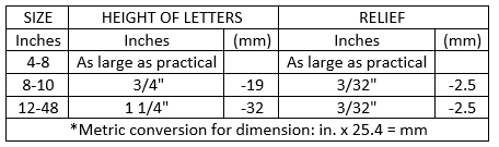
Delivery and Acceptance:
- a) All fittings shall be furnished with the manufacturers recommended accessories (glands, bolts and gaskets) required for proper installation.
- b) Each bidder will furnish an affidavit from the manufacturer that the fittings are of uniform quality and will fully comply with these Specifications.
- c) The affidavit shall also certify that the manufacturer has adequate equipment and quality control facilities to continually result in a finished product that will have the properties indicated herein.
- d) The manufacturer at the agreed point of delivery shall replace fittings not complying with the applicable provisions of ANSI/AWWA C11O/A21.10 and C111/A21.11.
Compact Ductile Iron Fittings (4″ to 54″)
General:
All fittings, unless otherwise specified by “Special” contract, hereinafter will be referred to as Ductile Iron fittings for use with Gray Iron, Ductile Iron and Polyvinyl Chloride pipe, shall conform to all applicable requirements in the latest revisions of ANSI/AWWA C153/A21.53 and C111/A21.11. Compact ductile iron fittings shall be manufactured by Clow, U.S. Pipe, Griffin, Tyler Pipe, Union Foundry, American and Star Pipe Products.
Material:
The material extrusion compounds, from which the iron is extruded and cast, shall comply with all applicable requirements for element quality as compared with class wall thickness.
Fittings Classifications and Dimensions:
- a) Pressure Rating Classification The Ductile Iron Fittings shall be rated for use with water at 73.4 degrees F and designed to withstand, without bursting, hydrostatic test of three times the rated working pressure.
- (i) 350 psi – for 3″ through 24″ diameter fittings unless otherwise specified.
- (ii) 150 psi for 54″ through 64″ diameter fittings unless otherwise specified.
- b) Dimension
- (i) Fittings shall be measured with suitable gauges at sufficiently frequent intervals to ensure that the dimensions comply with the requirements of this standard.
- (ii) The smallest inside diameter of the sockets and the outside diameter of the plain ends shall be tested with circular gauges.
- (iii) Other socket dimensions shall be measured as appropriate.
- c) Thickness –
- (i) Minus tolerances for the body metal thickness and the bell socket thickness shall not exceed the following:
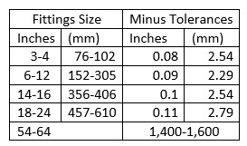
- d) Weight-
- (i) The tabulated weight reported by the manufacturer’s literature shall be the nominal weight of the fitting before application of any lining or special coating.
- (ii) The weight of any fitting shall not be less than the manufacturer’s nominal tabulated weight by more than 10 percent.
Fitting Strength Requirement:
- a) The standard acceptance test for the physical characteristics of ductile iron fittings shall be a tensile test from coupons from the same iron as the fittings.
- b) The test coupon shall be obtained from
- (1) the ASTM A536 keel block, modified keel block, or Y-block separately cast coupon;
- (2) the casting’s runner-bar system, provided that the diameter of the runner-bar at the location at which the coupon is selected is similar to the respective ASTM A536 coupon; or
- (3) the casting.
- c) The acceptance values of standard grade iron shall be 70-50-05, with acceptance values as follows: minimum tensile strength, 70,000 psi (483 MPa); minimum yield strength, 50,000 psi (345 MPa); and minimum elongation, 5 percent.
- d) Sustained Pressure Fittings having the classifications as stated in subtitle “C” should not fail, burst or weep when tested in accordance with the test method of ANSI/AWWA C153/A21.53.
Coatings and Linings:
- a) Outside Coating. The outside coating for general use under all normal conditions shall be a petroleum-asphaltic coating approximately 1 mil thick. The coating shall be applied to the outside of all fittings, unless otherwise specified. The finished coating shall be continuous, smooth neither brittle when cold nor sticky when exposed to the sun, and shall be strongly adherent to the fitting.
- Cement Mortar Linings. Cement-mortar linings shall be in accordance with ANSI/AWWA C104/A21.4.
Workmanship:
- a) Workmanship shall be of the highest level compatible with current commercial practice.
- b) The Ductile Iron fittings shall be homogeneous throughout and free of visible cracks, holes, or other injurious defects.
- The fittings shall be uniform in color, opacity, density and other physical properties.
Marking:
Fittings shall have distinctly cast on the outside of the body the identity of this standard, ANSI/AWWA C153/A21.4; the pressure rating; nominal diameter of the opening; manufacturer’s identification; the country where cast; the letters DI or word Ductile; and the number of degrees or fraction of the circle on all bends.
Delivery and Acceptance:
- a) All fittings shall be furnished with the manufacturers recommended accessories (glands, bolts and gaskets) required for proper installation.
- b) Each bidder will furnish an affidavit from the manufacturer that the fittings are of uniform quality and will fully comply with these Specifications.
- c) The affidavit shall also certify that the manufacturer has adequate equipment and quality control facilities to continually result in a finished product that will have the properties indicated herein.
- d) The manufacturer at the agreed point of delivery shall replace fittings not complying with the applicable provisions of ANSI/AWWA C153/A21.53 & C111/A21.11.
Butterfly Valves (Class 150 PSI)
General:
All butterfly valves furnished under these specifications shall conform to the latest revision of AWWA C504 and as supplemented herein. Valves shall be as manufactured by Henry Pratt “Groundhog type”.
Material:
- a) Valve body and flanges shall be constructed of cast iron ASTM A 126 Class B or ductile iron ASTM A 536 (65 45 12).
- b) Valve disc shall be constructed of cast iron ASTM A 126 Class B, cast iron ASTM A 48 Class 40 or ductile iron ASTM A 536 (65 45 12).
- c) Valve shafts shall be turned, ground and polished 18 8 Type 316 or Type 304 stainless steel.
- d) Rubber seats shall be Buna N and body mounted. Hard metal seats shall be disc mounted 316 stainless steel or NiChrome. Seat retention hardware, if used, shall be Type 316 stainless steel.
- e) Sleeve bearings shall be rigidly backed TFE nylon or bronze. Thrust bearings shall be as specified in AWWA C504. Bearing mating surfaces of ferrous material are unacceptable.
- f) Whenever valve components are to be made in conformance with ASA, ASTM or other standards that include test requirements or testing procedures, these shall be met by the valve manufacturer.
Classifications and Dimensions:
Butterfly valves shall be mechanical joint as indicated on the requisition or drawings. Valves shall be rated for 150 psi, unless otherwise specified, and shall turn clockwise to open.
Standard Requirements:
- a) The manufacturer shall furnish catalog data, including detailed illustrations and parts schedule giving the material of which parts are made to assure that the valves proposed fully comply with the specification. Operation and maintenance manuals shall be furnished as required.
- b) Valve body thickness shall be in strict accordance with Table 3 of AWWA Standard C504. Stops in the valve body will not be permitted. Mechanical joint ends shall conform to ANSI A21.11.
- c) Valve disc/shaft connection shall be made with stainless steel taper or dowel pins extending completely through the shaft and both sides of the disc. The use of bolts or setscrews is unacceptable.
- d) Shaft diameters shall meet the minimum requirements established in Table 4 of AWWA C504, latest revision.
- e) Rubber seats shall be body mounted. Rubber seats on the disc will not be permitted.
- f) Shaft packing shall be chevron V type or double O ring. O rings shall be housed in a removable corrosion resistant housing. Packing shall be replaceable from the outside without removing the valve shaft or bearings.
Workmanship, Painting and Testing:
- a) Workmanship shall be of the highest level compatible with current commercial practice.
- b) All surfaces shall be clean, dry and free from grease before painting. Surfaces, except seating and finished portions, shall be evenly coated with Amercoat 370 (black) in accordance with NSF/ANSI standard 61 and AWWA C550 or asphalt varnish in accordance with Federal Specification TT-C-494B and AWWA Standard C504.
- c) Hydrostatic and leakage tests shall be conducted in strict accordance with AWWA Standard C504. Certified copies of tests shall be provided upon request.
Marking:
- a) All butterfly valves shall have markings cast on the body and stamped on a stainless steel plate permanently attached to the valve.
- (i) The markings shall show the valve size, manufacturer, class and year of manufacture.
- (ii) The minimum size of cast letters shall be 2 inch for valves 16″ & larger.
Delivery and Acceptance:
- a) Each bidder shall furnish an affidavit from the manufacturer that the butterfly valves are of uniform quality and fully comply with these specifications.
- b) The affidavit shall also certify that the manufacturer has adequate equipment and quality control facilities to continually result in a finished product that will have the properties indicated herein.
- c) The manufacturer at the agreed point of delivery shall replace all butterfly valves not complying with these specifications.
Drawings and Data:
The manufacturer shall furnish catalog data including detailed illustrations describing the equipment proposed. Failure to furnish the required data will be cause for rejection of the bid. The successful bidder shall furnish four sets of operation and maintenance manuals.
Butterfly Valves (Class 250 PSI)
General:
All butterfly valves shall be of tight closing, rubber seat type with rubber seats that are securely fastened to the valve body. No metal to metal seating surfaces shall be permitted. Valves shall be bubble tight at rated pressures with flow in either direction, and shall be satisfactory for applications involving valve operation after long periods of inactivity. Valve discs shall rotate 90 degrees from full open position to the tight shut position. All valves shall be rated for 250 PSIG differential operating pressure. The rating shall be based on a design stress of 3 to 1 on the yield strength or 5 to 1 on tensile strength of the materials used. All valves shall be Henry Pratt Company, HP250 Groundhog type.
Valve Bodies and Flanges:
Valve bodies shall be constructed of cast iron ASTM A 126 Class B. Mechanical joint bell dimensions shall conform to AWWA C111 (ANSI A21.11). Slots, with the same width as the diameter of the boltholes, may be provided instead of holes in the bell flange only at those places where the body and bonnet interfere with the joint assembly. Two trunnions for shaft bearings shall be integral with each valve body.
Valve Discs:
Valve discs shall be constructed of cast iron ASTM A 48 Class 40 or ductile iron ASTM A 536 with type 316 stainless steel seating edge. Disc and shaft connection shall be made with stainless steel taper pins extending completely through the valve disc.
Valve Shafts:
All shafts shall be turned, ground, polished, and constructed of ASTM A 564, type 630 stainless steel.
Valve Seats:
Valve seats shall be of a rubber compound complying with AWWA C504 Section 3.5. Rubber seats shall be located in the valve body. Seats shall be securely anchored in place using a nonbonding epoxy wedge, or type 316 stainless steel retention hardware.
Valve Bearings:
Valves shall be fitted with sleeve type bearings. Bearings shall be corrosion resistant and self-lubricating. Bearings shall be Teflon lined with non-metallic backing.
Valve Operators:
Manual operators shall be of the traveling nut, self-locking link/lever type and shall be designed to hold the valve in any intermediate position between fully opened and fully closed without creeping or fluttering. Operators shall be equipped with independent mechanical stop limiting devices to prevent over travel of the disc in the open and closed positions. Stops located in the valve body are not permissible. Operator housings, supports and connections to the valve shall have provisions for at least four bolt mounting. All exposed operator-mounting bolts shall be stainless steel. Operators shall be equipped with a 2″ square operating nut and shall be fully gasketed and grease packed for buried service. Valves shall close with a counter-clockwise rotation of the nut.
Painting:
All surfaces of the valve shall be clean, dry and free from grease before painting. The valve surfaces except seating and finished portions shall be evenly coated with Amercoat 370 (black) in accordance with NSF/ANSI standard 61 and AWWA C550 or asphalt varnish in accordance with Federal Specification TT-C-494B and AWWA Standard C504.
Testing:
All valves shall be hydrostatic and leak tested. The leak test shall be performed at a differential pressure of 250 psig. The leak test shall be conducted with the body flanges in a horizontal plane. With the disc in the closed position, air pressure or water pressure shall be applied to the lower face of the disc for the full test duration. The upper surface of the valve disc shall be visible and shall be covered with a pool of water if air pressure is used to perform the test. There shall be no indication of air bubbles in the pool of water on the top of the disc during the test period. If water is used as a test medium, the valves shall be drop tight. The hydrostatic test shall be performed with the disc in a slightly open position. Internal hydrostatic pressure equal to 500 PSIG shall be applied to the inside of the valve body of each valve for a period of five minutes. During the hydrostatic test, there shall be no leakage through the metal, the end joints or the valve shaft seal.
Marking:
- a) All butterfly valves shall have markings cast on the body or on cast plates with raised letters, welded on the valve body.
- (i) The markings shall show the valve size, manufacturer, pressure rating and year of manufacture.
- (ii) The minimum size of letters shall be ½” inch for valves 16″ and larger.
Delivery and Acceptance:
- a) All butterfly valves shall be furnished with the manufacturers recommended accessories (glands, bolts and gaskets) required for proper installation.
- b) Each bidder shall furnish catalog data, spare parts list, assembly and disassembly repair instructions, and an affidavit from the manufacturer that the butterfly valves are of uniform quality and will fully comply with these specifications. The successful bidder shall furnish four sets of operation and maintenance manuals.
- c) The affidavit shall also certify that the manufacturer has adequate equipment and quality control facilities to continually result in a finished product that will have the properties indicated herein.
- d) The manufacturer at the agreed point of delivery shall replace all butterfly valves not complying with these specifications.
Gate Valves (AWWA C515)
General:
This standard covers reduced wall, resilient-seated gate valves with non-rising stems (NRS), including tapping and cut-in gate valves, for water supply service having a temperature range of 33°F to 125°F (0.6°C to 52°C). All resilient-seated gate valves furnished under these specifications shall conform to all applicable requirements in the latest revisions of ANSI/AWWA C515 unless otherwise noted herein. Valves shall be American Flow Control Series AFC 2500, Clow, Kennedy, EJ, M & H, Mueller and U.S. Pipe.
- a) Sizes: Gate valves covered by this standard are 2 in. (50 mm), 4 in. (100 mm), 6 in. (150 mm), 8 in. (200 mm), 10 in. (250 mm), and 12 in. (300 mm) NPS. Sizes refer to the nominal diameter of the waterway through the inlet and outlet connections and the closure area.
- b) Valve Pressure Rating: The minimum design working water pressure shall be 200 psig (1,380 kPa) for all sizes.
- c) Conditions and Material not covered. This standard is not intended to cover special conditions of installation or operation. Joint accessories for end connections, such as bolts, gaskets, glands, and follower rings, are not covered in this standard.
Material:
- a) All materials designated hereinafter, when used in valves produced under these Specifications shall conform to the requirements listed in AWWA C515 99 or the latest revisions.
- b) Joint materials for end connections such as bolts, gaskets, glands, follower rings, etc., are not covered in this standard.
- c) The requirements of AWWA, ANSI, ASTM, or other standards to which reference is made elsewhere in this document shall govern the physical and chemical characteristics of the valve components.
- d) Whenever valve components are to be made in conformance with AWWA, ANSI, ASTM, or other standards that include test requirements or procedures, such requirements or procedures shall be complied with by the valve Manufacturer. The records of all tests shall, if required by the Purchaser, be made available to him.
- e) Ductile iron shall conform to the requirements of ASTM A395 or ASTM A 536 and contain no more than 0.08 percent phosphorus.
- f) Copper alloys used in valves shall comply with the following:
- (i) Copper alloy valve components shall be made to ASTM-recognized alloy specifications with United Numbering System for Metals and Alloys (UNS) designations.
- (ii) Any copper alloy used in the cold-worked condition shall be capable of passing the mercurous nitrate test in accordance with ASTM B154.
- (iii) Copper alloys that contain more than 16 percent zinc shall not be used in water shown to promote corrosion in the form of dezincification or dealuminization. If aluminum bronze is used, the alloys shall be inhibited against dealuminization.
- (iv) Copper alloys that contain more than 16 percent zinc shall not contain less than 57 percent copper.
- (v) Copper alloys that contain 16 percent zinc or less shall not contain less than 79 percent copper.
- (vi) Valve components manufactured from some grades of manganese, bronze, or some other materials are subject to stress corrosion. The manufacturer shall design the valve and select materials to minimize stress corrosion.
- (vii) Copper alloys that contact drinking water shall not contain more than 8 percent lead (US Safe Drinking Water Act of 1986).
- g) Bolting materials, excluding joint accessories, shall have the physical strength requirements of ASTM A307 and shall have either regular square or hexagonal heads with dimensions conforming to ANSI B18.2.1. Bolts, studs, and nuts shall be ANSI stainless steel type 304.
- h) Disc Guides shall be cast integrally with the body of the valve.
- i) The ferrous material of the gate valve shall be made of ductile-iron or gray iron.
- j) Resilient seats shall be bonded or mechanically attached to the gate. The proof-of-design test method used for bonding or vulcanizing shall be ASTM D429; either method A or B. For method A, the minimum strength shall not be less than 250 psi (1,725 kPa). For method B, the peel strength shall not be less than 75 lb/in. (13.2 N/mm). All exposed mechanical attaching devices and hardware used to retain the resilient seat shall be of a corrosion-resistant material.
- k) O–rings shall meet the requirements of ASTM D2000 and have physical properties suitable for the application.
Classifications and Dimensions:
- All gate valves shall be of mechanical joint character with a 2″ square wrench nut and open right. The interior shall be coated with a fusion-bonded epoxy coating. The minimum design working water pressure shall be 200 psig (1,380 kPa) for all sizes.
Standard Requirements:
- a) The manufacturer shall furnish catalog data, including illustrations, and a parts schedule giving the material of which parts are made in sufficient detail to serve as a guide in the assembly and disassembly of the various Gate valves as well as in ordering repair parts.
- b) Resistance to Stress: All parts shall be designed to withstand, without exceeding the fatigue limit of the material or being structurally damaged,
- (i) The stresses resulting from an internal test pressure of twice the rated design working water pressure of the parts and,
- (ii) The combined stresses resulting from the full rated internal working pressure when the wedge or gates are moved across the seats, under full unbalanced working water pressure from the fully closed position to the point of opening, thence to complete closure.
- c) Structural design. All parts of all valves shall be designed to withstand
- (i) An internal test pressure of twice the rated design working pressure of the valve; and
- (ii) the full-rated internal working pressure when the closure member is cycled once from a fully open to a fully closed position against the full-rated unbalanced working water pressure. In addition to these pressure requirements, the valve assembly and the mechanism shall be capable of withstanding an input torque as follows: 4 in. (100 mm) NPS – 200 ft.-lb. (270 Nm); 6 in. (150 mm), 8 in. (200 mm), 10 in. (250 mm), and 12 in. (300 mm) NPS – 300 ft.-lb. (406 Nm).
- d) Flanged Ends: The end flanges of flanged valves shall conform to dimensions and drillings of ANSI/AWWA C110/A21.10 or ASME/ANSI B16.1, Class 125 unless explicitly provided otherwise in these specifications.
- e) Mechanical-Joint Ends: Mechanical-joint dimensions shall conform to ANSI/AWWA C110/A21.10, ANSI/AWWA C111/A21.11, or ANSI/AWWA C153/A21.53.
- f) F.I.P.T. x F.I.P.T. (Female Iron Pipe Thread): Threaded ends shall meet or exceed all applicable requirements of ANSI/AWWA C509 Standard and shall be certified to ANSI/NSF 61.
- g) Push-On Joint Ends. Push-on joint ends shall conform to the requirements of ANSI/AWWA C111/A21.11.
- h) Tapping-Valve Flanges
- (i) The flanged end of a tapping valve that forms a joint with the tapping sleeve shall conform to the dimensions of MSS SP-60 in sizes 4 in. (100 mm) through 12 in. (300 mm) NPS.
- (ii) The connecting flange of the tapping valve mating with the tapping machine must be parallel, concentric with the opposite flange, and concentric with the waterway to provide proper alignment for the tapping operation. The end flange of a tapping valve that forms a joint with the tapping machine shall conform to the dimensions of MSS SP-113.
- (iii) Size of Waterway: With the valve open, an unobstructed waterway shall be provided. The waterway shall have a diameter equal to or larger than the full nominal diameter of the valve. For tapping valves, the size of the waterway shall include appropriate clearance for the diameter of the tapping machine cutter recommended by the valve manufacture.
Workmanship:
- a) Workmanship shall be of the highest level compatible with current commercial practice.
- b) Unless otherwise specified by the purchaser, valve coatings, shall meet the performance requirements of Sec. 3.4.5 of Fed. Spec. TT-C-494b for water-based enamel coating or black asphalt coatings or ANSI/AWWA C550 for epoxy coatings, or equal.
Marking:
- Markings shall be cast on the bonnet or body, or stamped on a permanently affixed corrosion resistant tag of each valve. Markings shall show the manufacturer’s name or mark, the year the valve casting was made, the size of the valve, letters “C515,” and the designation of the working pressure, for example, “200W.” Special markings in addition to these can be supplied when specified by the purchaser.
Delivery and Acceptance:
- a) All gate valves shall be furnished with the manufacturers recommended accessories (glands, bolts & gaskets) required for proper installation.
- b) Each bidder shall furnish an affidavit from the manufacturer that the gate valves are of uniform quality and will fully comply with these Specifications.
- c) The affidavit shall also certify that the manufacturer has adequate equipment and quality control facilities to continually result in a finished product that will have the properties indicated herein.
- d) The manufacturer at the agreed point of delivery shall replace all gate valves not complying with the applicable provisions of AWWA C515.
Tapping Saddle With Outlet Sizes 3/4″, 1″ & 2″
General:
- a) All tapping saddles furnished under these specifications shall conform to all applicable requirements in the latest revisions of ANSI/AWWA C800, ASTM D 2000 and NSF/ANSI 61.
- (i) The tapping saddle shall have a sealing gasket on the outlet aperture and shall be of a “O-ring” design
- (ii) Tapping saddles with ¾” and 1″ outlets shall have AWWA tapered thread (CC).
- (iii) Tapping saddles with 2″ outlet shall have Female I.P. thread pattern. Threaded ends shall meet or exceed all applicable requirements of ANSI/AWWA C509 Standard and shall be certified to ANSI/NSF 61.
- (iv) The tapping saddles shall be designed for use with steel, cast iron, ductile iron PVC, high density polyethylene (SDR 17 or thicker) and asbestos cement pipe.
Material:
- a) Stainless Steel Tapping Sleeve:
- (i) Body: The tapping sleeves shall be 304 (18-8) stainless steel, or equal.
- (ii) Branch: The branch shall be 304 (18-8) stainless steel spin-extruded with high strength welds.
- (iii) Nuts: The nuts shall be heavy hex, of 304 stainless steel and lubricated to prevent galling or seizing.
- (iv) Bolts: The bolts shall be 304 (18-8) stainless steel, or equal, 5/8-inch NC threads.
- (v) Gaskets: The gaskets shall be of virgin Nitrile Butadiene Rubber (NBR) and be certified to NSF- 61 and ASTM D2000.
- b) Bronze Tapping Sleeve:
- (i) Body: The tapping sleeve shall be NSF 61 certified brass body.
- (ii) Straps: The strap shall be one piece, double strap design in 304L stainless steel.
- (iii) Threads: The threads shall be rolled threads in 304L stainless steel.
Sleeve Classification and Dimensions:
- a) Rating: The tapping saddle shall be rated for a minimum working pressure of 200 psi.
- b) Testing: The tapping saddle shall be capable of hydrostatic testing up to 1.5 times system pressure.
- c) OD Range: The tapping saddle shall have an outside diameter (OD) range that is inclusive of all designed pipe materials for each size of saddle.
Standard Requirements:
The manufacturer shall furnish catalog data, including illustrations, and a parts schedule giving the material of which parts are made in sufficient detail to serve as a guide in the assembly and disassembly of the various tapping sleeves as well as in ordering repair parts.
The following manufactured tapping saddles shall be considered acceptable for bidding purposes:
- a) Total Piping Solutions Triple-Tap T3
- b) Mueller BR2W Series
- c) Romac Style 202BS
Workmanship:
- a) Workmanship shall be of the highest level compatible with current, commercial practice.
- b) The tapping sleeves shall be uniform in color, density, and other physical properties.
Marking:
- a) All tapping sleeves shall have markings stenciled on the body of the sleeve.
- (i) The markings shall show the tapping sleeve size, manufacturer, part number, O.D. range and year of manufacture.
- (ii) The minimum size of letters shall be 1/2 inch in height.
- b) All tapping sleeves shall have markings so placed as to be readily discernible and legible.
Delivery and Acceptance:
- a) All tapping sleeves shall be furnished with the manufacturer’s accessories required for proper installation.
- b) Each bidder shall furnish an affidavit from the manufacturer that the tapping sleeves are of uniform quality and will fully comply with these Specifications.
- c) The affidavit shall also certify that the manufacturer has adequate equipment and quality control facilities to continually result in a finished product that will have the properties indicated herein.
- d) All tapping sleeves not complying with the applicable provisions of ASTM A 240, ASTM D 2000, and ANSI/AWWA 207/150, shall be replaced by the manufacturer at the agreed point of delivery.
Tapping Sleeve With Outlet Sizes 4″ or Greater
General:
All tapping sleeves furnished under these specifications shall conform to all applicable requirements in the latest revisions of ANSI/NSF 61 and ASTM D 2000. The BPU will determine based upon application which tapping sleeve is to be used.
Material:
- a) Body: The tapping sleeves shall have either a ductile iron body for mechanical joint type sleeve or carbon steel A-36 or equal for branch sealing type sleeve.
- b) Flange: The flange shall comply with MSS SP-60.
Sleeve Classification and Dimensions:
Rating: The tapping sleeves shall be rated for a minimum working pressure of 250 psi for outlet sizes 4 inch through 8 inch, 175 psi for 10 inch through 12 inch, and 150 psi for larger outlets and size-on-size sleeves.
Standard Requirements:
The tapping sleeve shall be a two-part sleeve that bolts together at the top and bottom. The tapping sleeve shall have either a branch-sealing gasket or mechanical joint gland gasket. The tapping sleeve shall be furnished with a 3/4-inch NPT test port plug for easy use.
The following manufactured tapping sleeves shall be considered acceptable for bidding purposes:
- a) Romac FTS420 Fabricated Steel
- b) Mueller H-16 Mechanical Joint Tapping Sleeve
Workmanship:
- a) Workmanship shall be of the highest level compatible with current, commercial practice.
- b) The tapping sleeves shall be uniform in color, density, and other physical properties.
Delivery and Acceptance:
- a) All tapping sleeves shall be furnished with the manufacturer’s accessories required for proper installation.
- b) Each bidder shall furnish an affidavit from the manufacturer that the tapping sleeves are of uniform quality and will fully comply with these Specifications.
- c) The affidavit shall also certify that the manufacturer has adequate equipment and quality control facilities to continually result in a finished product that will have the properties indicated herein.
- d) All tapping sleeves not complying with the applicable provisions of ASTM A 240, ASTM D 2000, and ANSI/AWWA 207/150, shall be replaced by the manufacturer at the agreed point of delivery.
Fire Hydrants
- General:
- All fire hydrants furnished under these specifications shall conform to all applicable requirements in the latest revisions of AWWA C502. Fire hydrants shall be as manufactured by Mueller Super Centurion 250, Clow Medallion, Waterous Pacer, and EJ.
- Material:
- a) All materials designated hereinafter shall, when used in hydrants produced under this standard, conform to the requirements designated below for each material listed. When reference is made to AWWA, ANSI, ASTM, or other standards, it is understood that the latest revisions shall apply.
- b) Whenever hydrant components are to be made in conformance with AWWA, ANSI, ASTM, or other standards, the hydrant manufacturer shall meet all test requirements or testing procedures specified therein. The records of such tests shall, if required by the Purchaser, be made available to him.
- c) All Gray Cast Iron shall conform to ASTM A126, Class B; or ASTM A48, Class 30 (Gray Iron Castings for Valves, Flanges, and Pipe Fittings).
- d) All Ductile Cast Iron shall conform to one of the following standards: ASTM A395 (Cast Ductile Iron Pressure Containing Parts for Use at Elevated Temperatures), or ASTM A536.
- e) All malleable iron shall conform to ASTM A47, ASTM A220, or ASTM A197.Malleable iron may be used for Structural parts, but not for pressure containing parts.
- f) Steel shall conform to ASTM A108 (Cold Finished Carbon Steel Bars and Shafting), ASTM A575, or ASTM A576.
- g) Hydrant components made of bronze or brass shall be made to ASTM or Copper Development Association (CDA) recognized alloy specifications.
- h) Body bolts and nuts shall develop the physical strength requirement of ASTM A307, Grade B, and may be of any dimension listed in ASA B18.2. Bolts and nuts shall be either cadmium plated (ASTM A165, Type NS), or zinc coated (ASTM A123), or rustproof by some other process (Parkerizing, Sherardizing, or the like) disclosed to and acceptable to the Purchaser.
- i) Stuffing box seals may be used instead of “0” ring seals. When used, the width of the packing shall be at least 1/4 in., and the depth of packing space shall be at least four times its width.
- j) When stuffing boxes are used, they shall be made either of Grades A or D bronze or Cast Iron.
- k) If glands are made of solid bronze, the bronze shall be Grade A, D or E. If glands are made of bronze brushed Cast Iron, the bronze shall be Grades A, B, or D.
- l) “O” rings shall be compounded to meet ASTM D2000 and have physical properties suitable for the application.
- m) Gasket material shall be of rubber composition, or paper free from corrosive ingredients, either alkaline or acid. “O” ring seals may be used for gaskets.
- Classification and Dimensions:
- a) The thickness of the wall of the barrel shall be not less than the thickness specified for Class 250 water pipe of like diameter. Minimum wall thickness shall conform to AWWA C502.
- b) The minimum thickness of the wall of the barrel and base at any point shall be as shown in AWWA C502, Table 3. The wall thickness of barrels of fractional-inch diameters shall be that of the next larger diameter. For statically cast barrels, a minus tolerance of 0.02 in. over areas not exceeding 8 in. in length in any direction shall be permissible.
- c) All fire hydrants shall be as specified with a 4″ or 6″ D 150 mechanical joint inlet and a specified bury depth. The hydrant shall have a 4 1/2″ or 5 1/4″ nominal size of main valve openings, as specified, open left and comply with the latest revisions of AWWA C502 unless otherwise specified.
- d) Operating nut shall be national standard pentagon head.
- e) Nozzle casting shall be provided with Board of Public Utilities’ Thread Pattern as follows: See A-172 in this section.
- Standard Requirements:
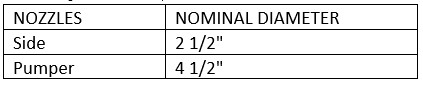
- a) The manufacturer shall furnish catalog data, including illustrations and a parts schedule, giving the material of which parts are made in sufficient detail to serve as a guide in the assembly and disassembly of the various fire hydrants as well as in ordering repair parts.
- b) The operating threads of the hydrant shall be designed to avoid the working of any iron or steel parts against either iron or steel. Either the threaded portion of the operating stem or its threaded stem kneader sleeve shall be made of bronze as specified in Sections 3.2.9.5 and 3.2.9.6 in AWWA C502.The operating stem and nut shall have square, V, one-half or modified V, Acme, or modified Acme threads. The lead of the threads shall be such that not less than eight complete turns will be required to close a 4 in. hydrant; ten complete turns to close a 5 in. hydrant and twelve complete turns to close a 6 in. hydrant. The minimum number of turns for intermediate sizes shall be that designated for the next larger size.
- c) The design factor of safety of the operating mechanism shall be not less than five, and shall be based on the foot-pounds of torque required for the closing and opening of the hydrant at 150 psi working water pressure. Hydrants shall show no signs of injury and shall be capable of being opened or closed without difficulty following application of an operating torque of 200 ft. lb. at the operating stem nut of the hydrants standing open and in a direction to open them further, and of closed hydrants in a direction to close them further. The torque requirements apply only to hydrants of 5 ft. bury or less.
- d) All iron parts shall be thoroughly cleaned and all surfaces (inside and outside) shall be coated with asphalt varnish where subjected to direct burial.
- e) All iron parts located above the ground line shall be thoroughly cleaned and thereafter painted in the shop with two (2) coats of paint of a durable and waterproof composition.
- Workmanship:
- a) Workmanship shall be of the highest level compatible with current commercial practice.
- b) All parts shall conform to the required dimensions and shall be free from defects that will prevent proper functioning of the hydrant.
- c) All machined parts shall be made to template or gage.
- d) All joints shall be faced true and shall be watertight when subjected to the water pressure for which the hydrant is designed.
- e) All iron parts receiving bronze mounting shall be made true and smooth, and the bronze mounting shall be finished to fit.
- f) All casting shall be clean and sound, without defects that will impair their service no plugging, welding, or repairing of such defects will be allowed.
- g) All like parts of hydrants of the same model and size produced by the same manufacturer shall be interchangeable.
- Marking:
- All hydrants shall have permanent markings identifying the manufacturer by name, initials, or abbreviations in common usage and designating the size of the main valve openings and the year of manufacture. Markings shall be so placed as to be readily discernible and legible after hydrants have been installed.
- Painting:
- a) Exterior All ferrous metal parts of the hydrant, inside and outside, shall be thoroughly cleaned and then painted as follows:
- (i) All exposed exterior surfaces below the ground line and exposed interior surfaces below the main valve shall be coated with asphalt varnish and shall be covered with two coats, the first being allowed to dry thoroughly before the second is applied.
- b) Interior All interior surfaces above the main valve, except machined surfaces such as the threaded portion of the operating stem or nut, which must fit closely with the adjacent parts, shall be coated with asphalt varnish or primer.
- c) Shop coating of hydrant top section The outside of the hydrant top section shall be thoroughly cleaned and then painted with a coat of primer. A second coat of primer or paint of a color specified by the purchaser shall be applied. Colors should be selected from Federal Standard 595A.
- d) The exterior portion of the fire hydrant shall be painted safety red.
- a) Exterior All ferrous metal parts of the hydrant, inside and outside, shall be thoroughly cleaned and then painted as follows:
- Delivery and Acceptance:
- a) All fire hydrants shall be furnished with the manufacturer’s recommended accessories (glands, bolts, and gaskets) required for proper installation.
- b) Each bidder shall furnish an affidavit from the manufacturer that the fire hydrants are of uniform quality and will fully comply with the Specifications.
- c) The affidavit shall also certify that the manufacturer has adequate equipment and quality control facilities to continually result in a finished product that will have the properties indicated herein.
- d) The manufacturer at the agreed point of delivery shall replace all fire hydrants not complying with the applicable provisions of AWWA C502.
5/8″, 3/4″, 1″, 1.5″ & 2″ Meters
General:
All meters shall conform to the AWWA Standards C 700 for cold-water positive displacement except as amended herein.
Material:
The material from which the meters are produced shall comply with applicable requirements for element quality in the latest revisions of NSF/ANSI 61 and AWWA C 700.
Classifications and Dimensions:
All registers shall be straight reading in cubic feet, display a low flow indicator for leak detection and shall be hermetically sealed. Each meter, when delivered to the purchaser, shall be supplied with the same register that was used during the factory test. The meters shall have the following minimum register capacities:
- a) 5/8″ through 2″ 100,000,000
Standard Requirements:
- a) Magnetic drives will be required on all 5/8″ through 2″ meters.
- b) All 5/8” through 1” meters shall have threaded ends.
- c) All 1.5” and 2” meters shall have flanged ends.
- d) Frost protection devices shall be provided in accordance with AWWA (C 700, Sec. 3.5) where required.
- e) The manufacturer’s serial number shall be stamped on all meter register lids and the main case.
- f) The following manufactured meters shall be considered acceptable for bidding purposes:
- (i) Neptune T 10 Series (w/additional register warranty)
- (ii) BadgerRecordall DiscSeries
- g) Where required, bottom plates shall be made of cast iron or synthetic polymer as specified by bid request. Stainless steel bolts shall secure bottom plates.
- h) Meters shall be manufactured for wire sealing.
- i) Each bidder shall supply catalogs for meters and parts with price list.
- j) Registers shall be solid-state encoder registers measuring in cubic feet. They shall digitally display nine digits, flow indicator, rate of flow measured in CFM and direction of flow.
- k) Signal transmission must be compatible with Elster AMI system. Signal transmission shall include eight-digit remote meter reading, tamper evident alarms and low battery warning.
- l) Registers shall have 6-ft wire lead with Nicor connector.
- m) Each meter shall be equipped with Rex-3 module with Nicor connector.
Workmanship:
The manufacturer shall guarantee all meters for a period of ten (10) years and register assembly units for a period of fifteen (15) years from the date of shipment against all defects in material and workmanship. The meter main case, chamber, and nutating disc or oscillating piston shall be considered as one unit, and the complete register shall be considered as one unit for the guarantee purposes. Should any unit be found to be defective due to workmanship or materials within the respective guarantee periods, it shall be replaced on a complete exchange basis per unit. Any additional guarantee by the manufacturer shall be stated in his bid.
Delivery and Acceptance:
- a) Each bidder shall furnish an affidavit from the manufacturer that the meters are of uniform quality and will fully comply with these specifications.
- b) The affidavit shall also certify that the manufacturer has adequate equipment and quality control facilities to continually result in a finished product that will have the properties indicated herein.
- c) The Manufacturer at the agreed point of deliver shall replace all meters not complying with the applicable provisions of AWWA C700.
3″ Meters and Larger
General:
All meters 3” or larger must be of the following types and conform to the pertaining AWWA standards; Turbine (AWWA C701), Compound (AWWA C702), Fire Service Type (AWWA C703) or Electromagnetic/Ultrasonic Type (AWWA C715). The BPU will determine based upon application which meter is to be used.
Material:
The material from which the meters are produced shall comply with applicable requirements for element quality in the latest revisions of NSF/ANSI 61 and NSF/ANSI 372.
Classifications and Dimensions:
All registers shall be straight reading in cubic feet, display a low flow indicator for leak detection and shall be hermetically sealed. Each meter, when delivered to the purchaser, shall be supplied with the same register that was used during the factory test.
Standard Requirements:
- a) All meters shall have a Unitized Measuring Element (UME) for ease in calibration and replacement.
- b) Fire Service Type meters shall be Underwriters Laboratory (UL) listed and Factory Manual (FM) approved.
- c) The manufacturer’s serial number shall be stamped on all meter register lids and the main case.
- d) The following manufactured meters shall be considered acceptable depending on use for bidding purposes:
- (i) Neptune TRU/FLO Compound Meter
- (ii) Neptune HP Turbine Meter
- (iii) NeptuneHP Protectus III Fire Service Meter
- (iv) Badger Recordall FSAA Meter
- (v) Amco evoQ4 Meter
- e) Meters shall be manufactured for wire sealing.
- f) Each bidder shall supply catalogs for meters and parts with price list.
- g) Registers shall be solid-state encoder registers measuring in cubic feet. They shall digitally display nine digits, flow indicator, rate of flow measured in CFM and direction of flow.
- h) Signal transmission must be compatible with Elster AMI system. Signal transmission shall include eight-digit remote meter reading, tamper evident alarms and low battery warning.
- i) Register shall have 25-ft wire lead with Nicor connector.
- j) Each meter shall be equipped with Rex-3 module with Nicor connector.
Workmanship:
The manufacturer shall guarantee all meters for a period of ten (10) years and register assembly units for a period of fifteen (15) years from the date of shipment against all defects in material and workmanship. The meter main case, turbine, chamber, and nutating disc or oscillating piston shall be considered as one unit, and the complete register shall be considered as one unit for the guarantee purposes. Should any unit be found to be defective due to workmanship or materials within the respective guarantee periods, it shall be replaced on a complete exchange basis per unit. Any additional guarantee by the manufacturer shall be stated in his bid.
Workmanship:
a) Each bidder shall furnish an affidavit from the manufacturer that the pipe is of uniform quality and will fully comply with these Specifications.
b) The affidavit shall also certify that the manufacturer has adequate equipment and quality control facilities to continually result in a finished product that will have the properties indicated herein.
c) The manufacturer at the agreed point of delivery shall replace pipe not complying with the applicable provisions of AWWA C111, C150 and C151.
3/4″ and 1″ Corporation Stops
General:
All Ball Type Corporation Stops, hereinafter referred to as corporations, furnished under these Specifications shall conform to all applicable requirements in the latest revisions of AWWA C800.
Material:
The material extrusion compounds from which the corporations are extruded shall comply with applicable requirements for element quality as compared with product dimension, AWWA C800.
Classifications and Dimensions:
- a) Openings on each side of the corporation shall be as follows:
- (i) Side 1 – AWWA tapered thread (CC)
- (ii) Side 2 – Pack Joint type for use with Type “K” copper tubing and polyethylene plastic tubing (PE4710)
- b) Corporations shall be less check with 360° turn operation.
Standard Requirements:
- a) The following brands of corporations shall be considered competitively acceptable:
- (i) Mueller 300 Ball Corporation Valve
- (ii) Ford FB1000 Ballcorp
- b) Corporations shall be one piece, closed bottom design ball valve.
- c) Corporations shall meet a minimum working pressure rating of 300 psi.
Workmanship:
- a) Workmanship shall be of the highest level compatible with current commercial practice.
- b) The corporations shall be homogeneous throughout and free of visible cracks, holes, foreign exclusions or other injurious defects.
Delivery and Acceptance:
- a) Each bidder shall furnish an affidavit from the manufacturer that the material is of uniform quality and will fully comply with these Specifications.
- b) The affidavit shall also certify that the manufacturer has adequate equipment and quality control facilities to continually result in a finished product that will have the properties indicated herein.
- c) The manufacturer at the agreed point of delivery shall replace corporations not complying with the applicable provisions of AWWA C800.
3/4″ and 1″ Ball Type Curb Stops
General:
All Ball Type Curb Stops, hereinafter referred to as Curb Stops, furnished under these Specifications shall conform to all applicable requirements in the latest revision of AWWA C800.
Material:
The material extrusion compounds from which the Curb Stops are extruded shall comply with applicable requirements for element quality as compared with product dimension, AWWA C800.
Classifications and Dimensions:
- a) Openings on each Side shall be as follows:
- (i) Side 1 – Pack Joint type for use with Type “K” copper tubing and polyethylene plastic tubing (PE4710).
- (ii) Side 2 – Female I.P. thread pattern. Threaded ends shall meet or exceed all applicable requirements of ANSI/AWWA C509 Standard and shall be certified to ANSI/NSF 61.
- b) Curb Stops shall be less check with 360° turn operation type.
Standard Requirements:
- a) The Curb Stops shall be designed to be leak minimum.
- b) The Curb Stops shall be designed for lifetime self-lubrication.
- c) The Curb Stops shall be manufactured as follows:
- (i) 3/4″ – Ford Ball Valve Curb Stop 41-333-NL
- (ii) 1″ – Ford Ball Valve Curb Stop 41-444-NL
- (iii) 3/4″ – Mueller 300 Ball Curb Valve P-25155N
- (iv) 1″ – Mueller 300 Ball Curb Valve P-25155N
Workmanship:
- a) Workmanship shall be of the highest level compatible with current commercial practice.
- b) The Curb Stops shall be homogeneous throughout and free of visible cracks, holes, foreign exclusions or other injurious defects.
Delivery and Acceptance:
- Each bidder shall furnish an affidavit from the manufacturer that the material is of uniform quality and will fully comply with these specifications.
2″ Ball Type Curb Stops
General:
All Ball Type Curb Stops, hereinafter referred to as Curb Stops, furnished under these Specifications shall conform to all applicable requirements in the latest revision of AWWA C800.
Material:
The material extrusion compounds from which the Curb Stops are extruded shall comply with applicable requirements for element quality as compared with product dimension, AWWA C800.
Classifications and Dimensions:
- a) Openings on each Side shall be as follows:
- (i) Side 1 – Male I.P. thread pattern. Threaded ends shall meet or exceed all applicable requirements of ANSI/AWWA C509 Standard and shall be certified to ANSI/NSF 61.
- (ii) Side 2 – Female I.P. thread pattern. Threaded ends shall meet or exceed all applicable requirements of ANSI/AWWA C509 Standard and shall be certified to ANSI/NSF 61.
- b) Curb Stops shall be less check with 360° turn operation type.
Standard Requirements:
- a) The Curb Stops shall be designed to meet 300 psi working pressure rating.
- b) The Curb Stops shall be designed for lifetime self-lubrication.
- c) The following brands of Curb Stops shall be considered competitively acceptable:
- (i) Mueller 300 Ball Curb Valve B-20285N-3
- (ii) Ford Ball Valve Curb Stop B81-777-NL
Workmanship:
- a) Workmanship shall be of the highest level compatible with current commercial practice.
- b) The Curb Stops shall be homogeneous throughout and free of visible cracks, holes, foreign exclusions or other injurious defects.
Delivery and Acceptance:
Each bidder shall furnish an affidavit from the manufacturer that the material is of uniform quality and will fully comply with these specifications.
Approved Water Meter and Backflow Drawing
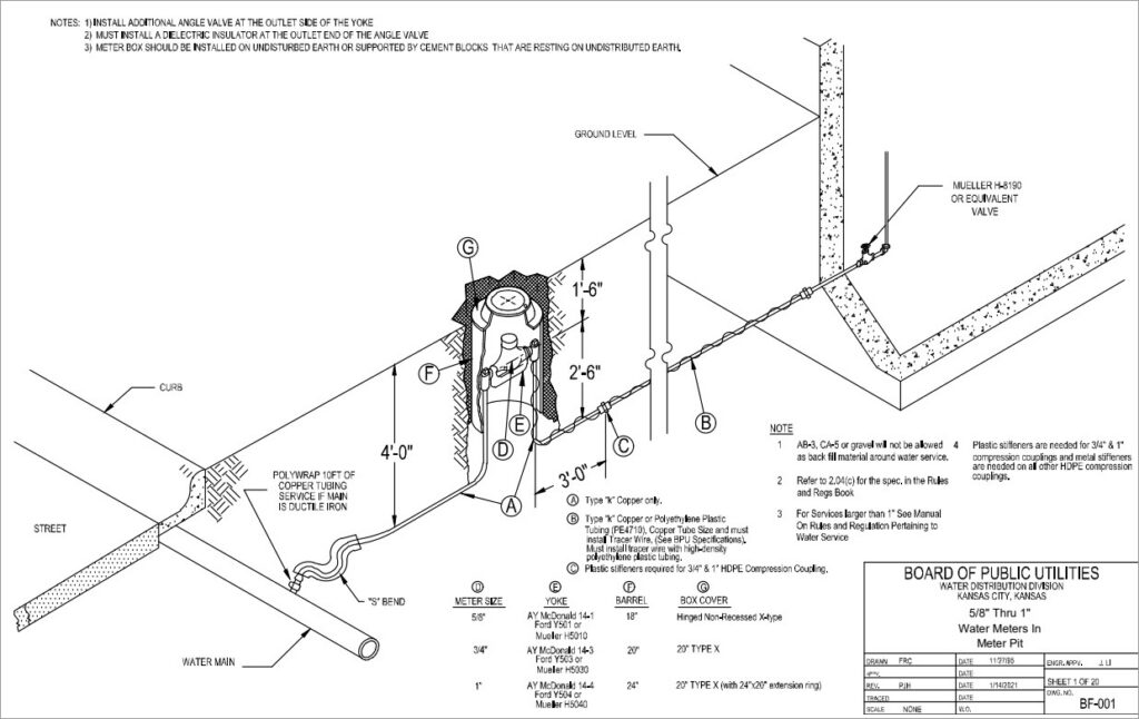
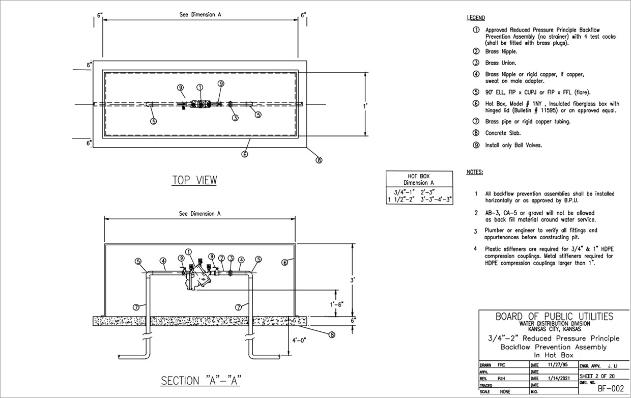
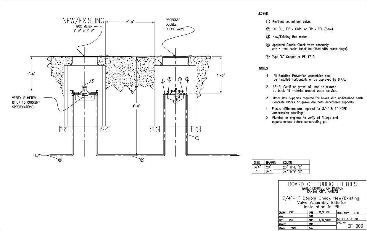
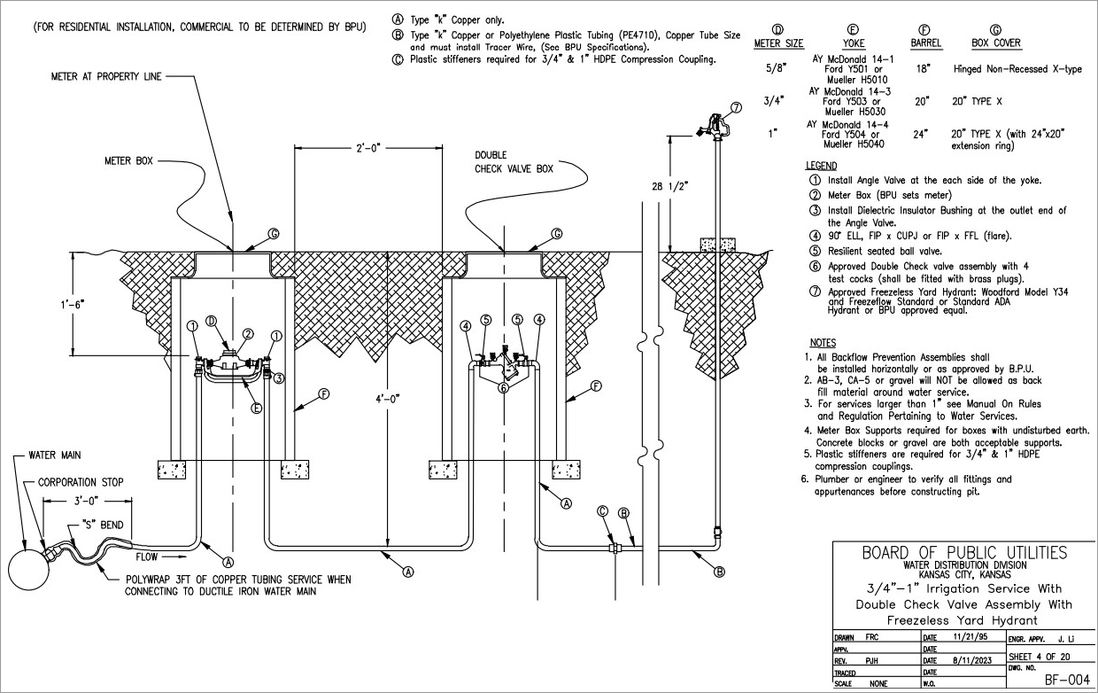
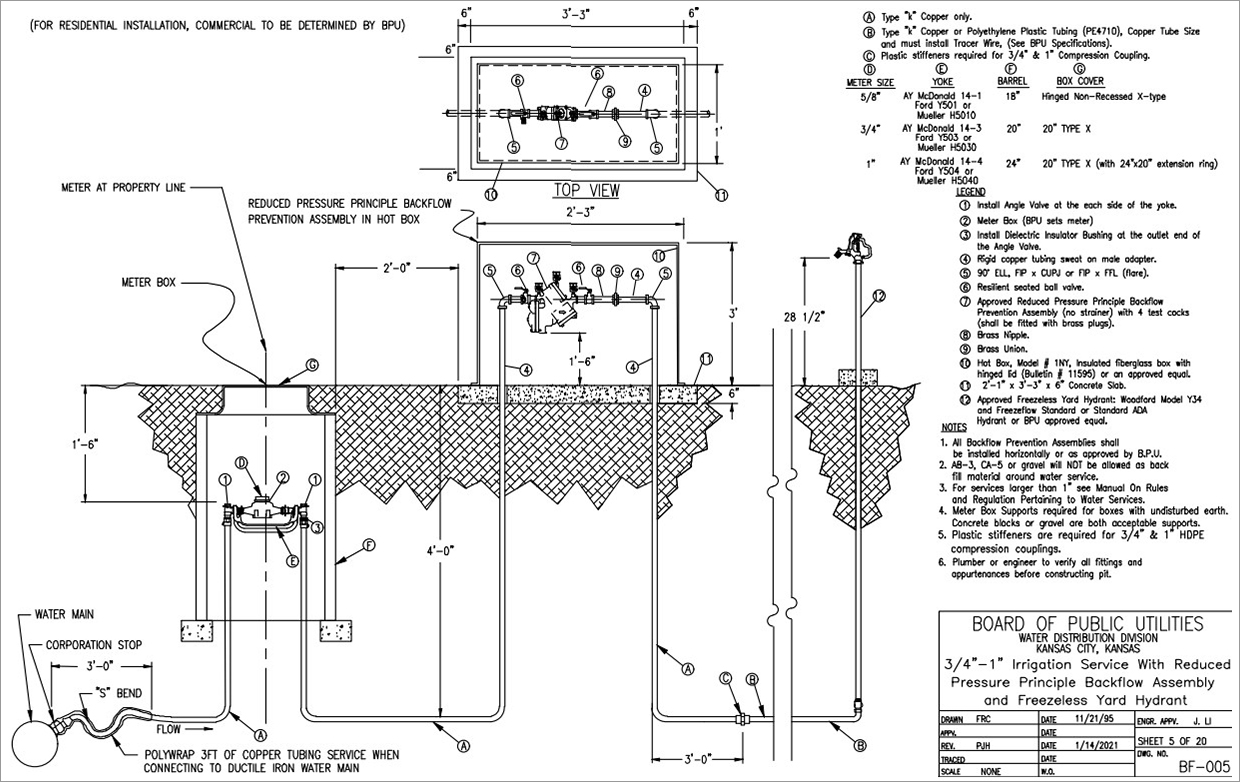
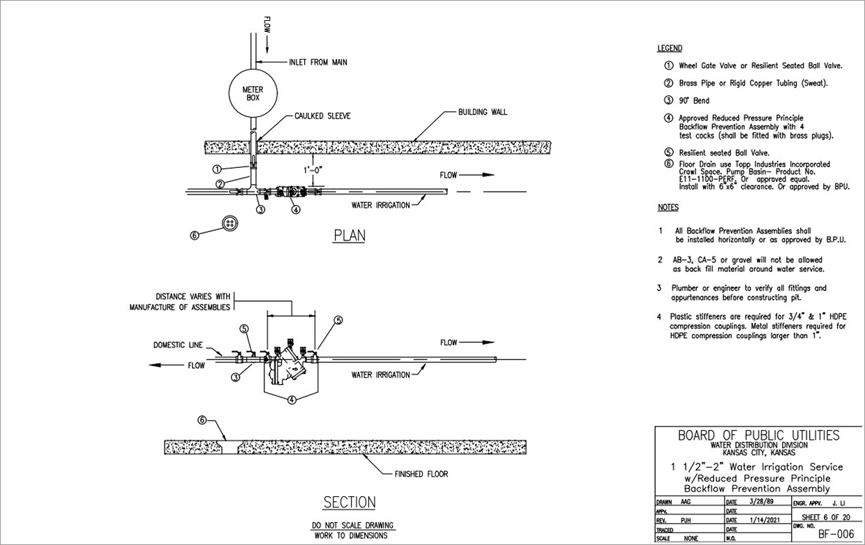
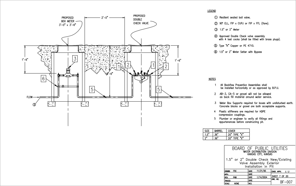
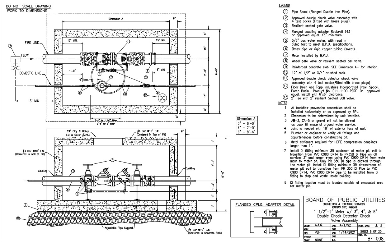

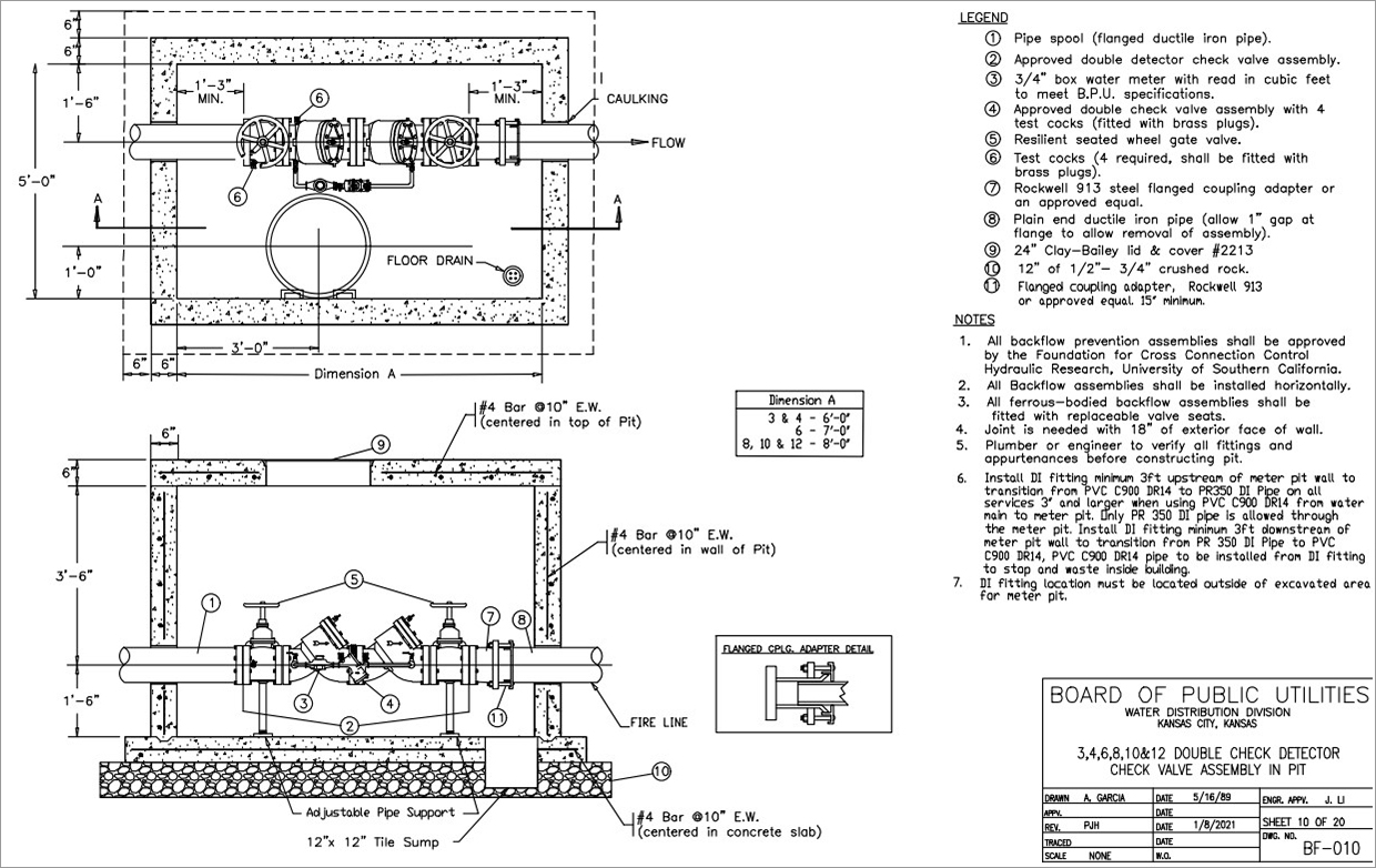
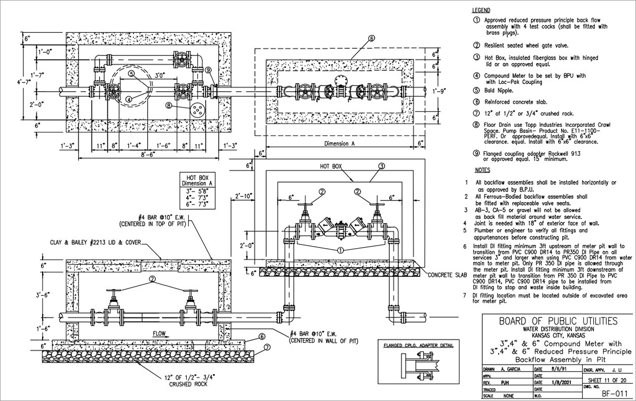
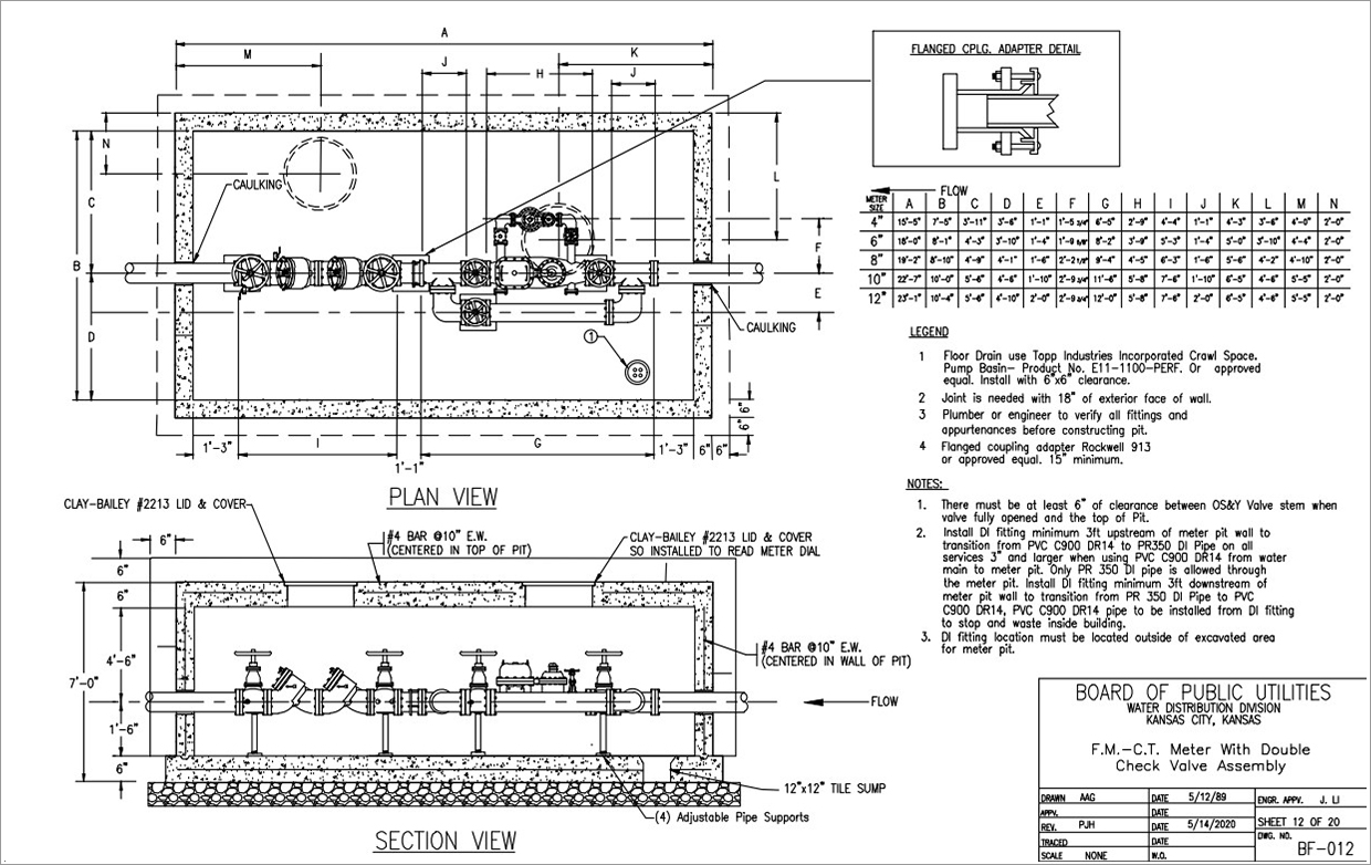
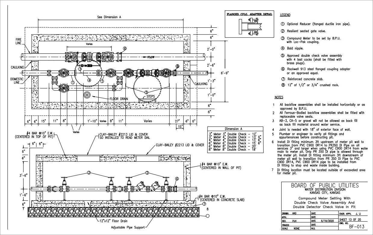
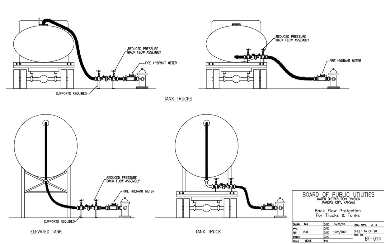
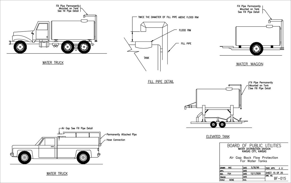
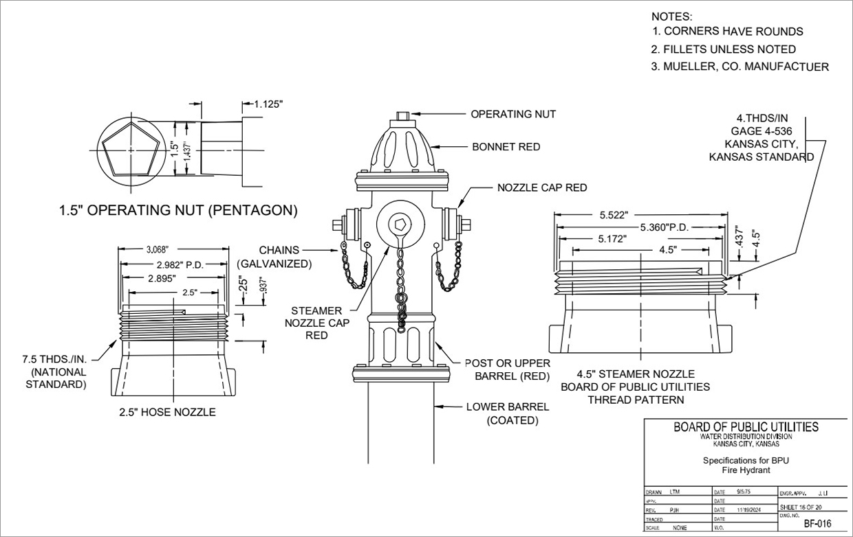
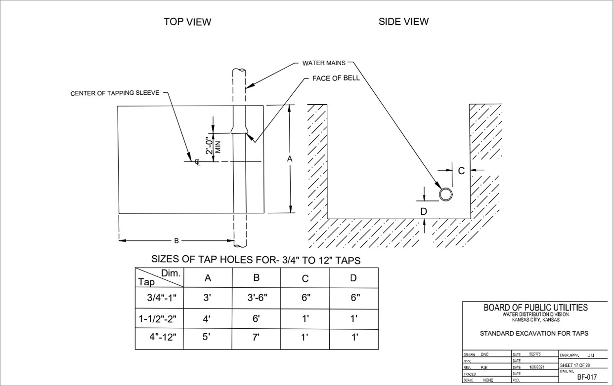
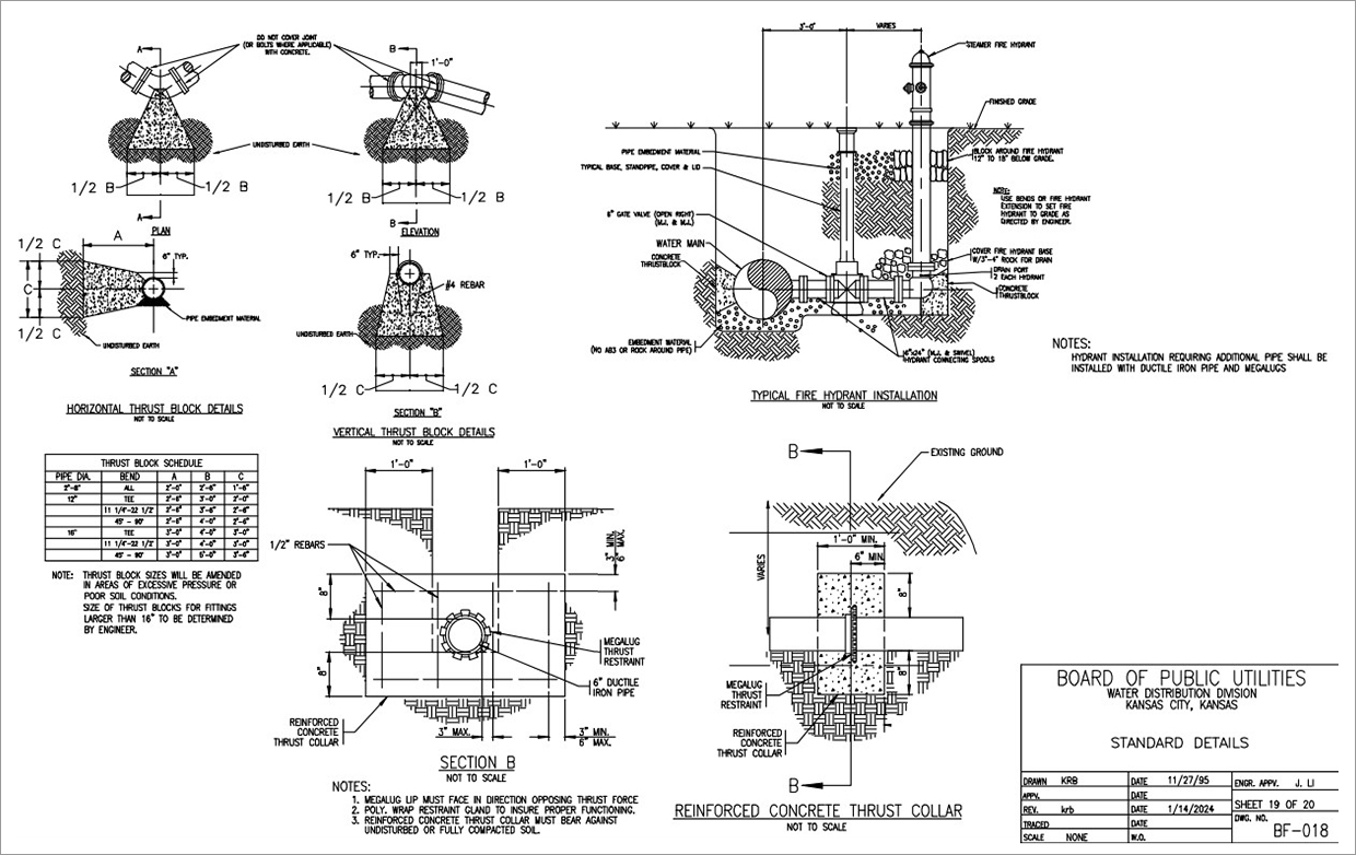
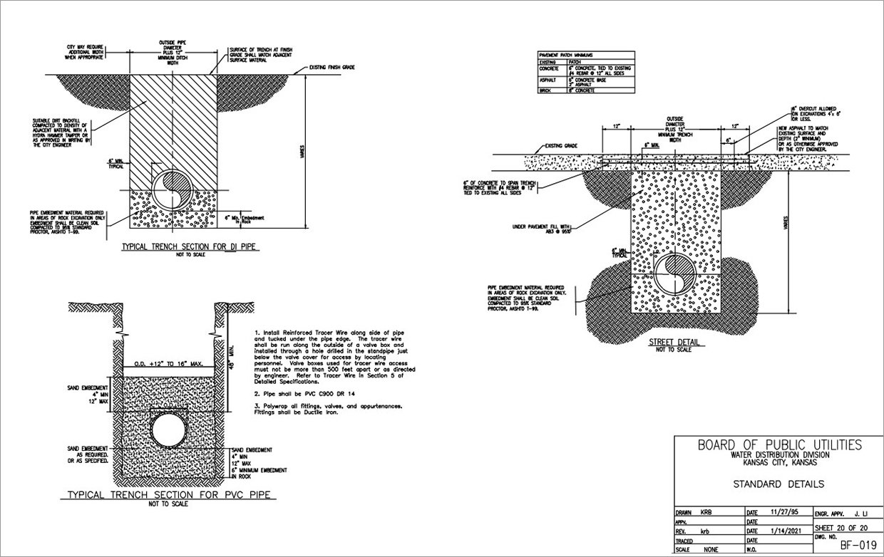

Need Assistance?
Contact Customer Care. We’re here to help.